22.2Roadway Configurations
Many roads lead to the path, but basically there are only two: reason and practice.Bodhidharma, Buddhist monk, 6th century
The location of the segregated busway within a specific roadway is a design decision that offers more options than might be immediately apparent. Busway configuration, also known as alignment, is critical to achieving fast and efficient operations by minimizing the potential conflicts with turning cars, stopping taxis, and unloading delivery trucks. Because of this, The BRT Standard awards the highest points to those configurations that minimize those conflicts that happen at the curb the most: two-way busways in the central verge of the roadway, two-way busways that run adjacent to an edge condition like a waterfront, and bus-only corridors, like a transit mall. A two-way busway that runs on the side of a one-way street is awarded fewer points. The reason for the point drop is a concern for safety as pedestrians are unlikely to expect traffic to come from the opposite direction. One-way busways in the median of a one-way street are awarded even fewer points and one-way busways that run alongside the curb of a one-way street fewer still. Virtual lanes are awarded the least points.
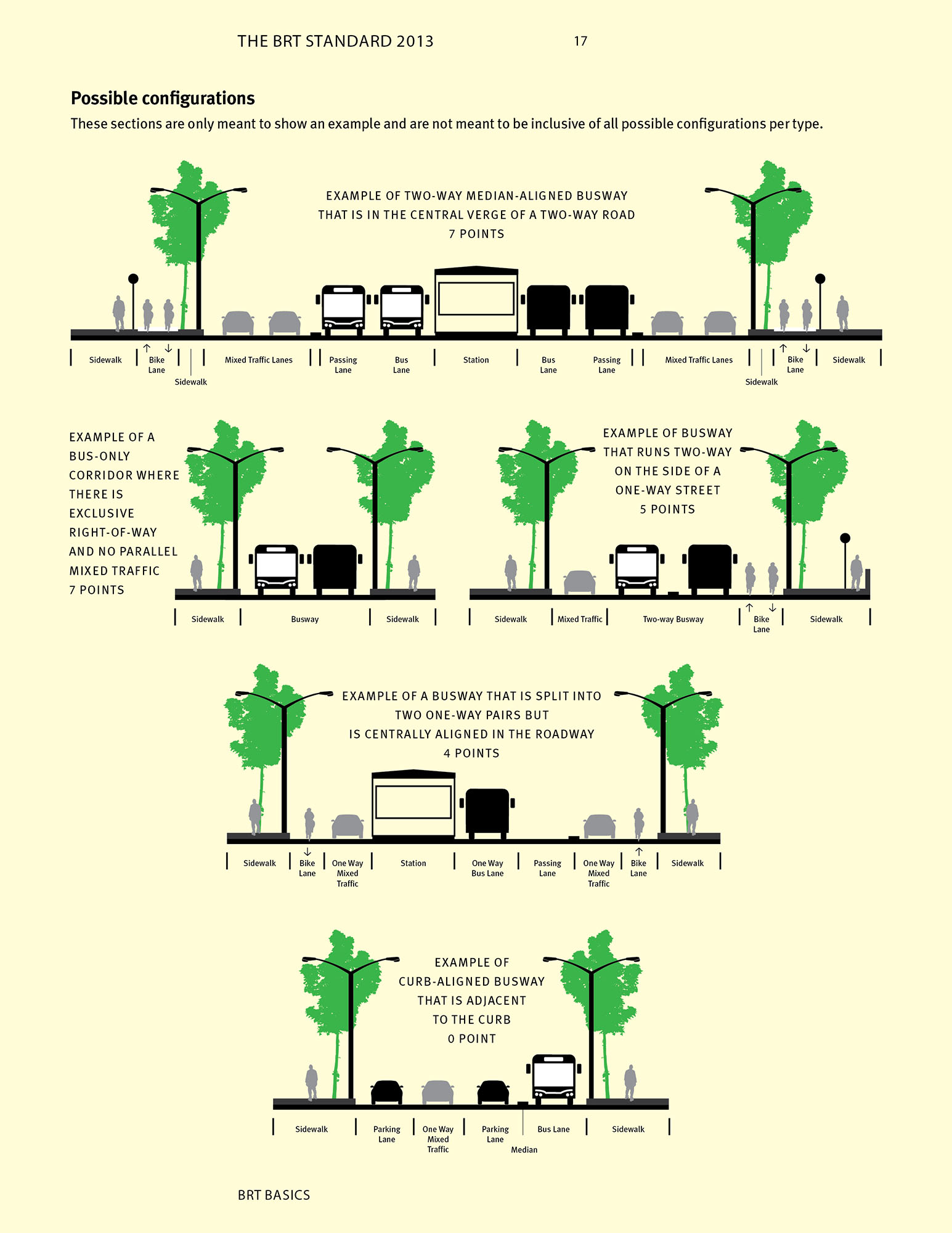
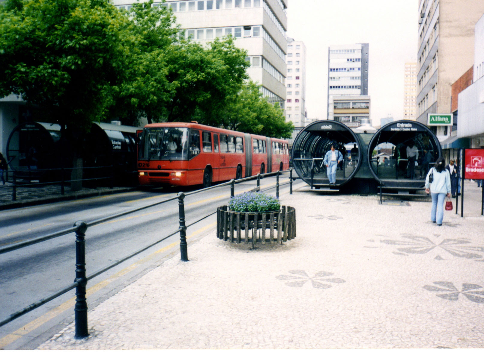
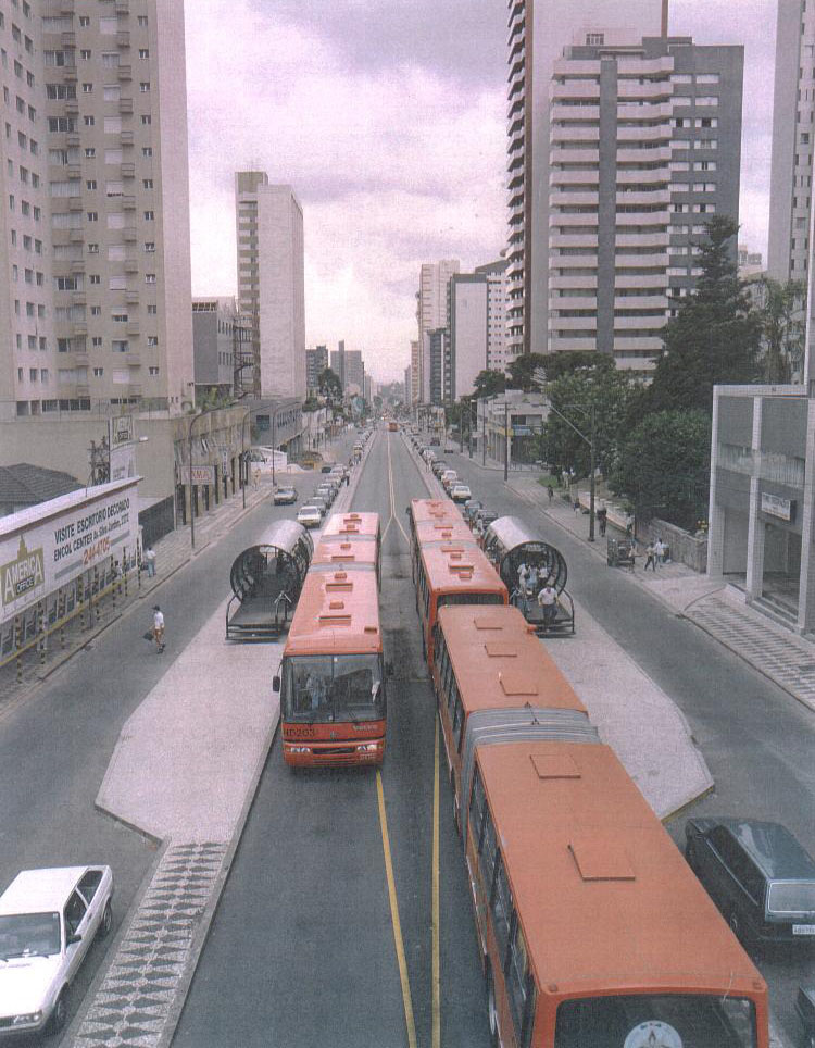
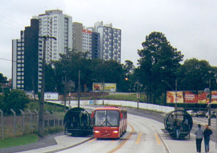
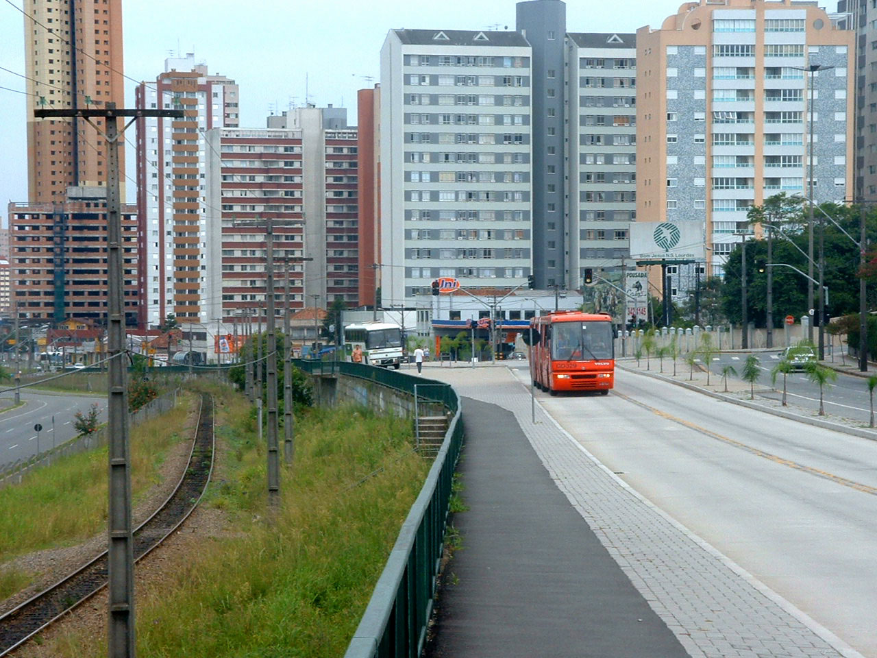
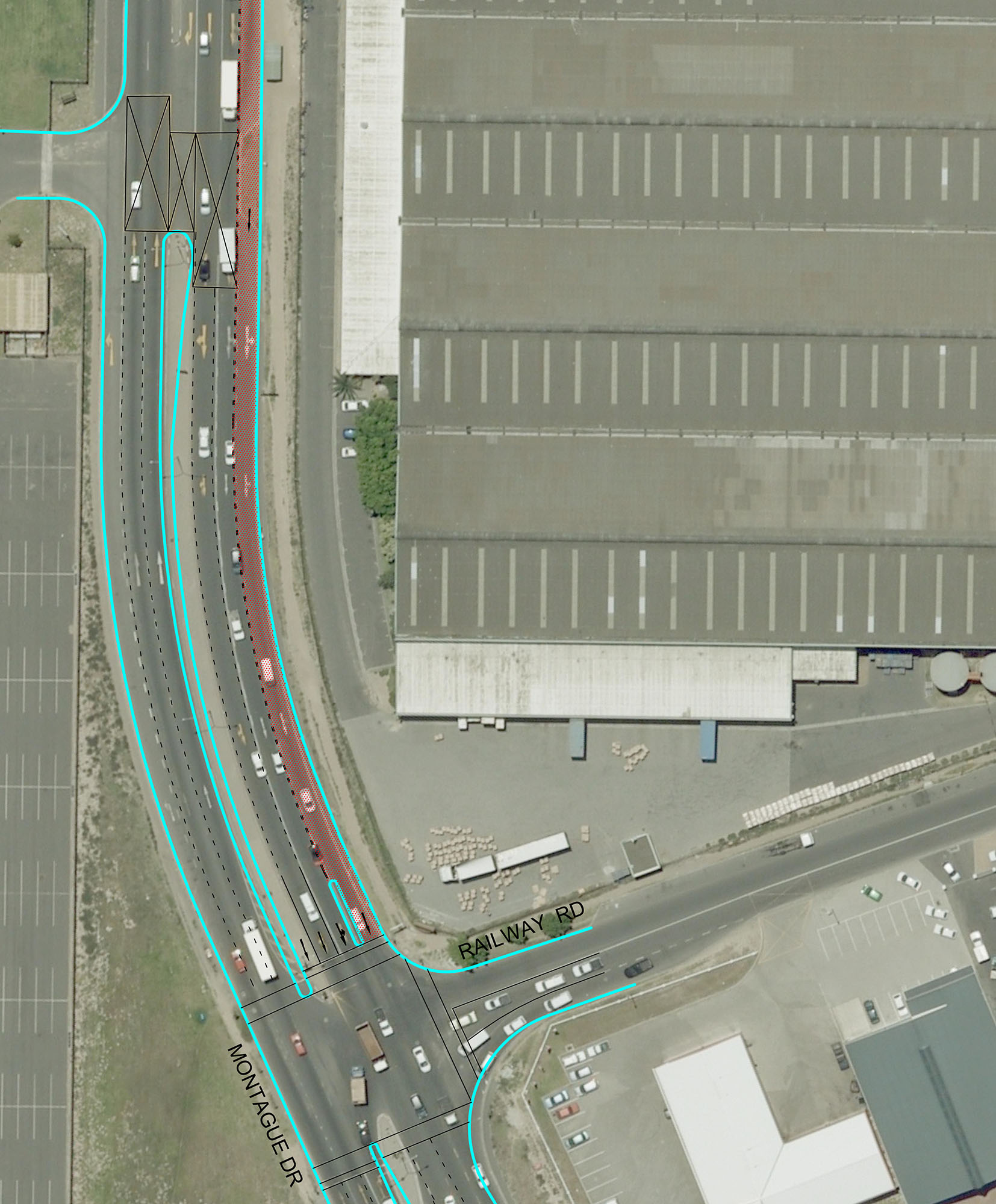
A corridor may have multiple configurations over its length. Like many other design decisions associated with BRT, there is no one correct solution to roadway configuration. Much depends on the local circumstances. Johannesburg, South Africa, has a two-way median-aligned busway until it gets into the downtown where it splits into one-way, median-aligned busways running on one-way streets. Curitiba, Brazil, uses center lanes, both lanes on the side, and streets exclusively for BRT (Figures 22.9, 22.10, and 22.11). Curitiba essentially tailors the roadway configuration to the particular situation on the given road segment.
Box 22.2 The Example of Dar es Salaam, Tanzania
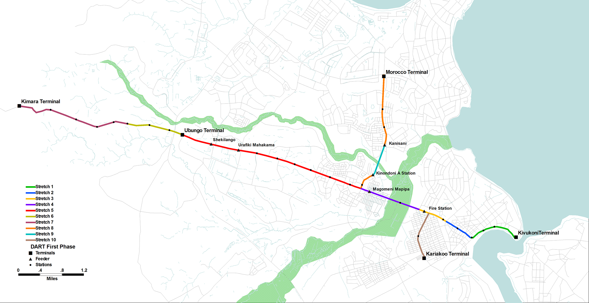
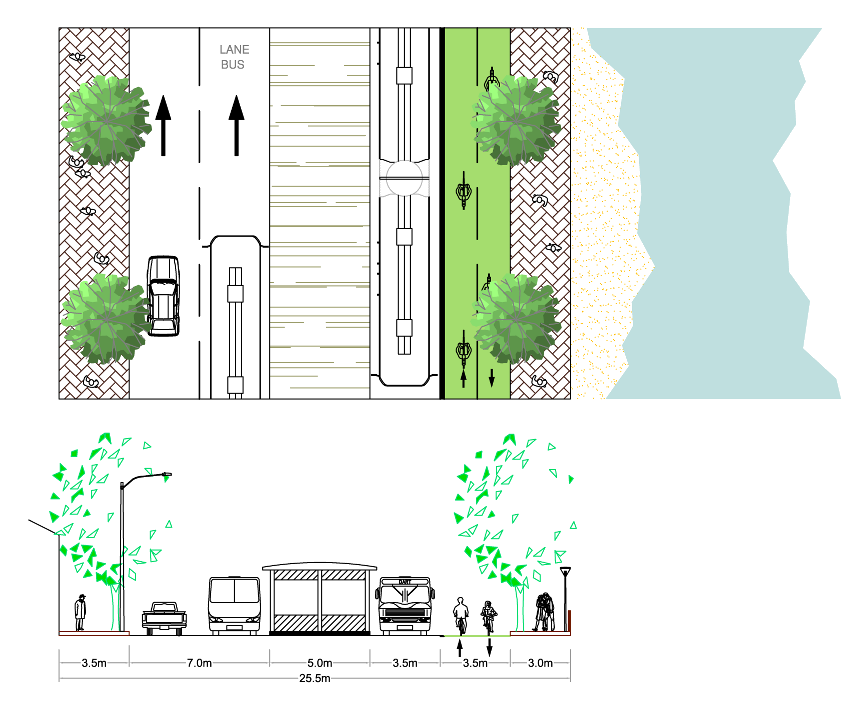
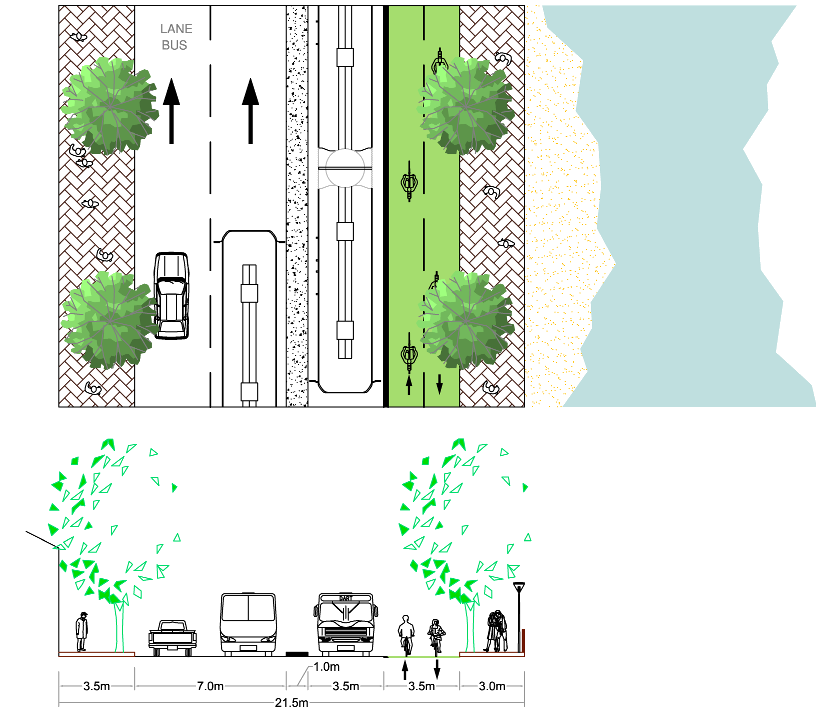
Stretch 1 is located along the waterfront and its typical cross sections varies from 25.5 meters at station locations to 21.5 meters in between stations. Its design characteristics include:
- Two 3.5-meter wide BRT lanes, one per direction;
- A 3.5-meter wide mixed-traffic lane in the southeast bound direction only;
- A 3.5-meter wide bikeway lane on the ocean side on the same road way level, separated from the vehicle lanes by concrete separators;
- A 3-meter pedestrian’s boulevard will be provided on the ocean side;
- Retaining walls will be required in some parts where there is a steep slope of more than 2 meters and fills will be required along the coastline.
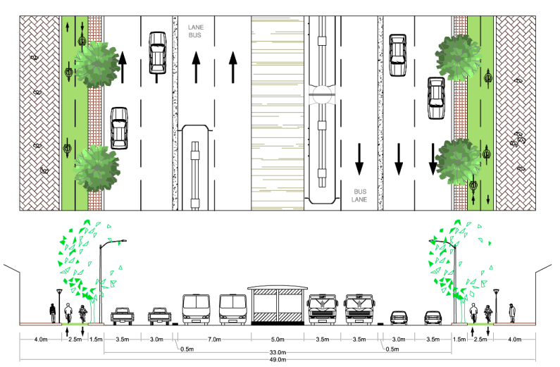
In Stretch 5 (Figure 22.16 below), the cross section design varies from 49 meters at stations to 38.5 meters in between stations. The section characteristics include:
- 2.5-meter wide bikeway on both sides of the road;
- 4-meter sidewalks on both sides;
- 6.5-meter lanes per direction for mixed traffic on both sides;
- 7-meter lanes per direction for BRT vehicles at stations;
- 3.5-meter lane per direction for BRT vehicles between stations;
- 1-meter wide median separating the BRT vehicles;
- 1.5-meter wide planting strip between bikeway and mixed-traffic lanes.
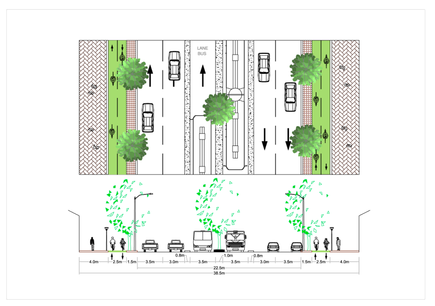
Following are the typical configurations for BRT corridor design to consider in the conceptual design phase and that should become the basis for the detailed engineering.
Box 22.3 Options for Narrow Roadways
Areas with narrow road widths, such as central business districts (CBDs) and historic centers, present many challenges to BRT developers (Figure 22.50). The density of activity and architectural nature of these areas may mean that less road space is available for a surface-based public transport system. At the same time, CBDs and historic centers are prime destinations for customers, and thus such areas should be included in the system’s network. Without access to central destinations, the entire system becomes considerably less useful to the potential customer base.
In general, there are at least ten different solutions to designing BRT systems through an area with extremely narrow road widths:
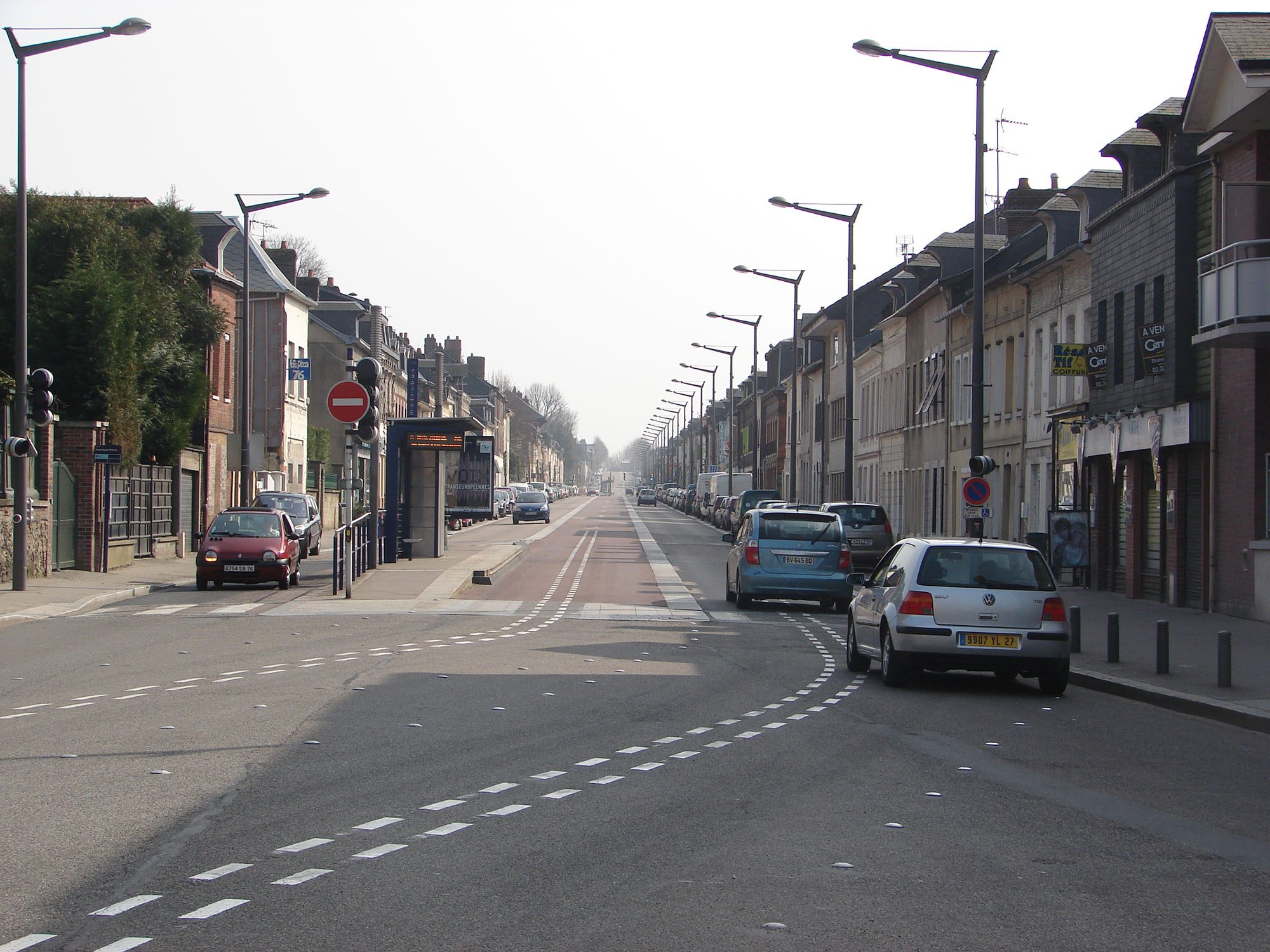
- Median busway and single mixed-traffic lane (e.g., Rouen, France);
- Transit malls and transit-only corridors;
- Split routes (two one-way services on parallel roads);
- Virtual lanes;
- Use of median space;
- Road widening;
- Grade separation;
- Fixed guideway;
- Single-lane operation or virtual lanes;
- Staggered stations/elongated stations.
22.2.1Median Busways
The most common option is to locate the busway in the center median or in the center two lanes (Figure 22.7). The BRT Standard awards full points for a median busway alignment. This is because the central verge of a roadway encounters fewer conflicts with turning vehicles than those closer to the curb, due to alleys, parking lots, etc. Additionally, while delivery vehicles and taxis generally require access to the curb, the central verge of the road usually remains free of such obstructions.
The median location also permits a central station to serve both busway directions. The BRT Standard awards full points under the “Center Stations” metric for a single station serving both directions of travel, allowing for easier transferring between directions or routes. A median station permits customers to select multiple routing options from a single station platform. A single station reduces infrastructure costs in comparison to the construction of separate stations for each direction. For more information about station configurations, see the next section.
22.2.2Curbside Busways
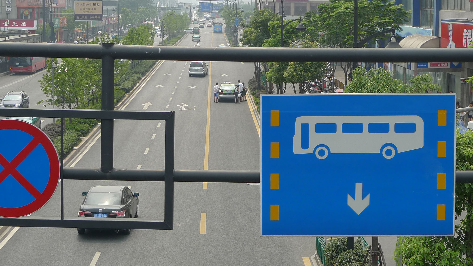
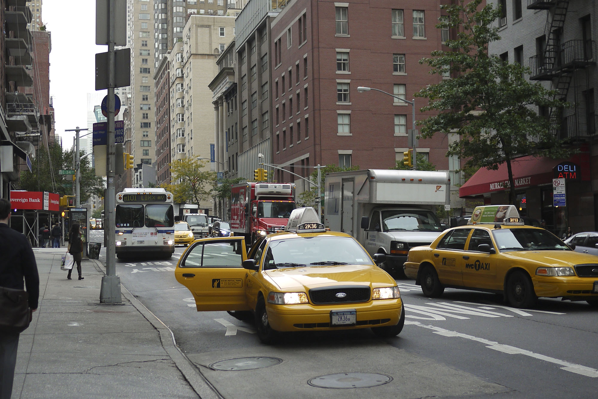
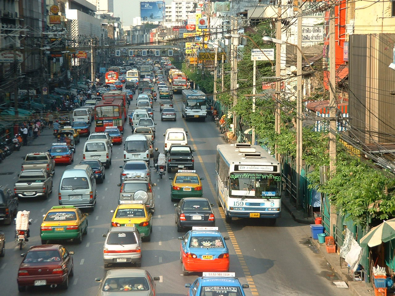
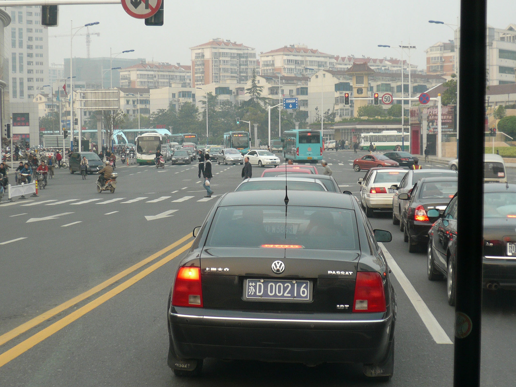
While it is typical to find conventional bus lanes at the curbside, it is rare for BRT to place the busway on the sides of the roadway. The BRT Standard awards no points for this configuration under the “Busway Alignment” metric, as curb lanes rarely function as intended. Curb lanes have conflicts with turning traffic, stopping taxis, delivery vehicles, and non-motorized traffic, greatly reducing the system’s capacity. Achieving capacities of more than five thousand customers per hour per direction is quite difficult if turning vehicles frequently interfere with busway operations. Curbside busways create the potential for the entire busway to be stopped due to a single taxi picking up a customer, a policeman temporarily parking, an accident, or a turning vehicle trapped behind high pedestrian-crossing volumes (Figure 22.17).
22.2.3Side-Aligned, Two-Way Busway Configuration
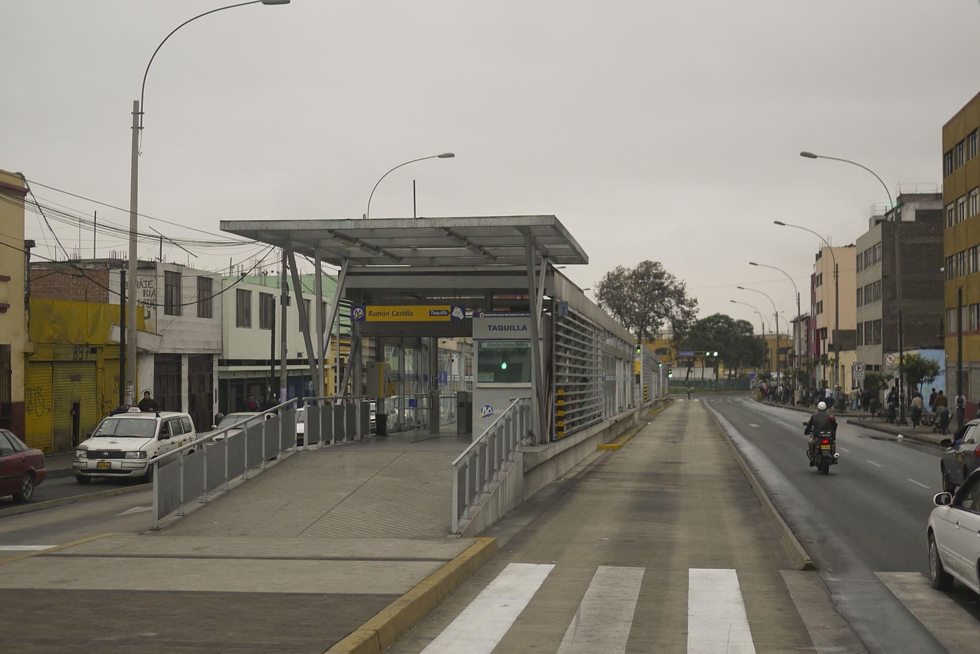
While curb-aligned busways generally fail due to turning conflicts with mixed traffic, placing two-way busways along the side of the roadway can work for certain roadway segments. If a roadway is bordered by green space (e.g., a large park), water (e.g., ocean, bay, lake, or river frontage), or open space, then there may be no turning conflicts for long distances, in which case side alignment may actually be preferable to median alignment. The BRT Standard awards the highest points under the “Busway Alignment” metric for side-aligned busways that are adjacent to such an edge condition. A key to choosing this type of alignment is the absence of access to development along a particular corridor edge, i.e., a park, an airport boundary wall, etc.
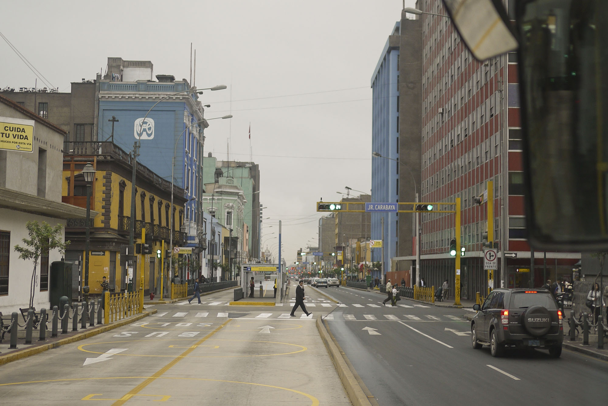
Where such an edge condition does not exist, it is still possible to consider other side-aligned options. Lima has implemented a two-lane, two-way busway adjacent to a two-lane, two-way general-traffic roadway (Figure 22.19). Intersections along a side-aligned busway can be problematic, but can be dealt with by using traffic signals and roundabouts.
22.2.4Fixed Guided Busways
Since a BRT vehicle is typically 2.6 meters wide, it is possible that a lane just slightly wider than this amount could suffice. Under normal operating conditions, a driver will require a road width of approximately 3.5 meters to safely maintain position within the lane, and 3 meters at the station, since the driver will slow down to pull adjacent to the boarding platform. However, if a vehicle is physically restrained by a guidance mechanism, then a lane width of 3 meters is possible.
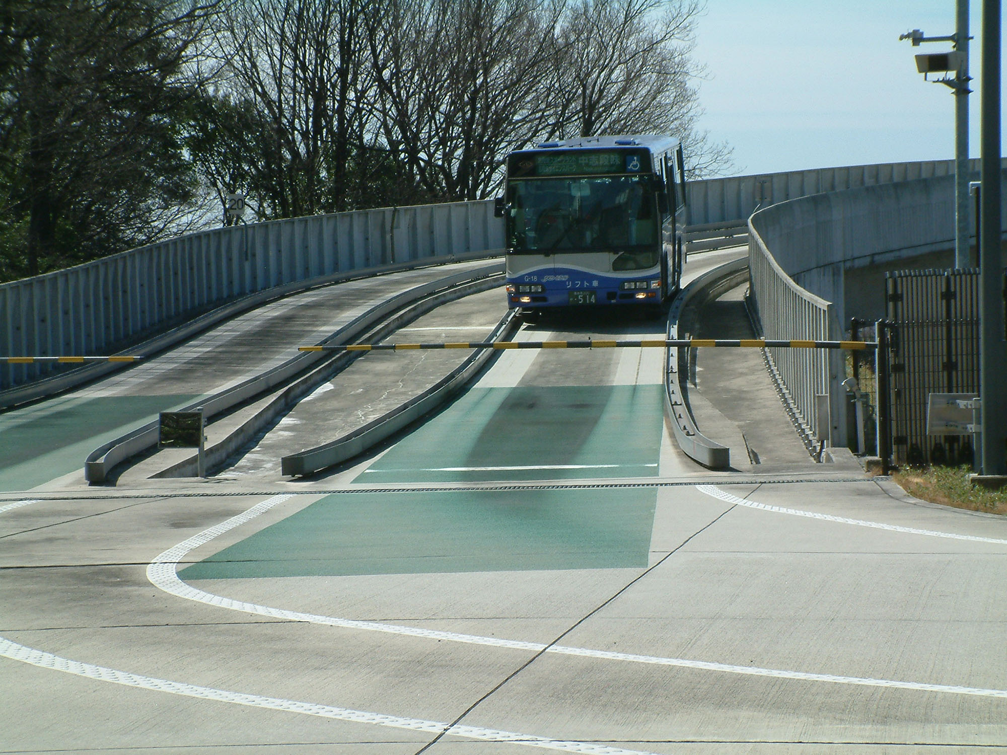
Physical guidance systems are employed on BRT systems in Adelaide, Australia; Bradford, United Kingdom; Essen, Germany; Leeds, United Kingdom; and Nagoya, Japan. A side-mounted guidance wheel maintains the vehicle’s position within the lane (Figures 22.21 and 22.22). A slight trench in the roadbed has also been used reasonably successfully in the Netherlands for short sections. Likewise, optical or magnetic guidance systems are also possible.
In instances when reducing lane width by approximately 0.9 meter is of great value, then a fixed-guideway system can be an option to consider. Guidance systems also provide other advantages, such as safer vehicle operation and higher operating speeds. The chief disadvantage is the added infrastructure cost associated with the side wheel and the guidance track. Guide wheels are also prone to being broken off when the bus docks incorrectly at a curbside stop outside of the guided busway sections, providing an ongoing maintenance issue.
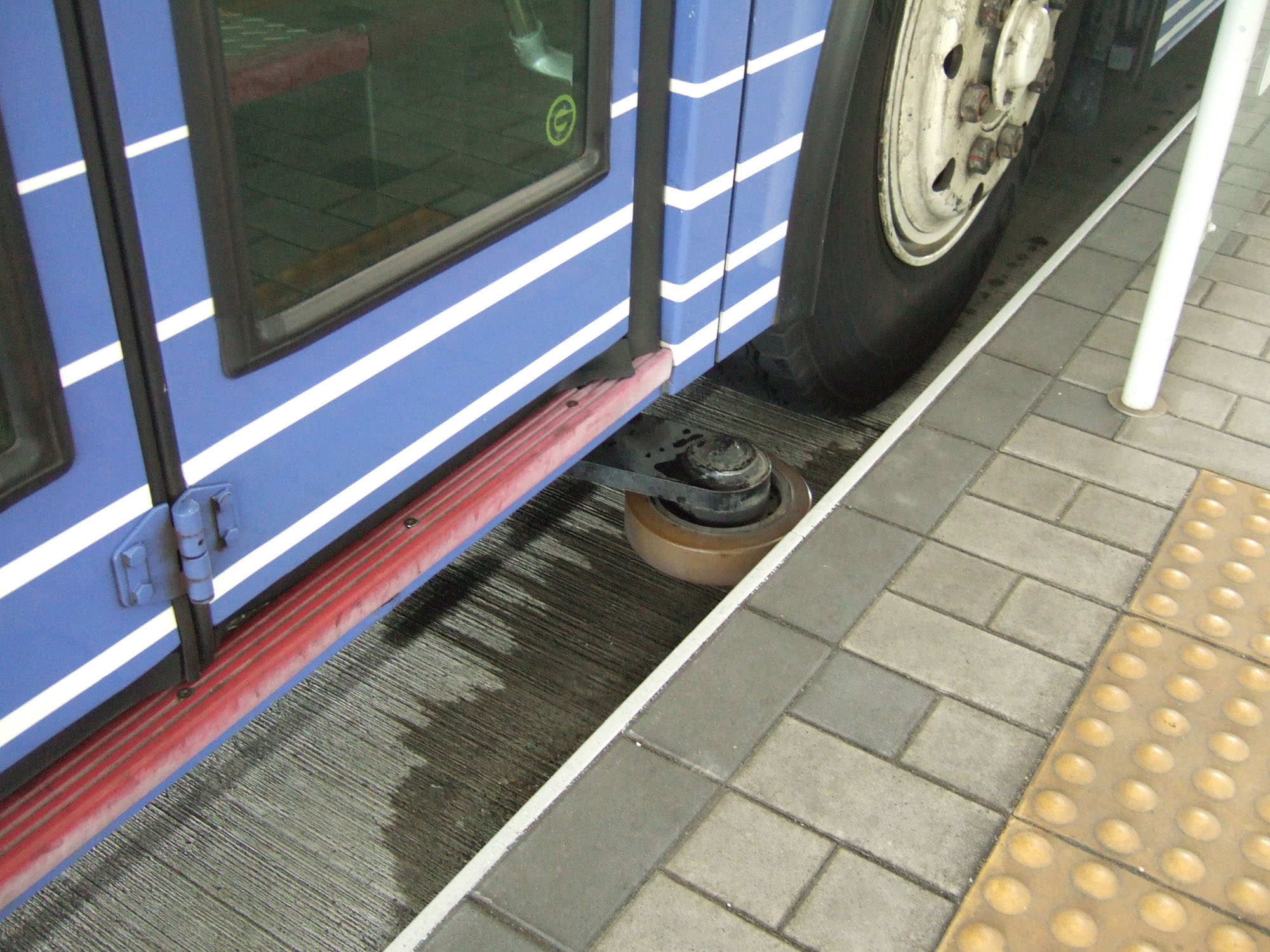
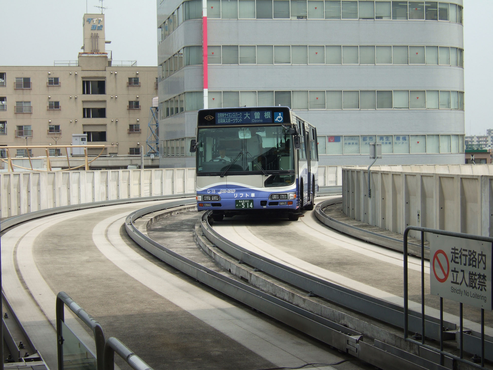
Table 22.1Advantages and Disadvantages of Guided Busway Systems
| Advantages | Disadvantages |
|---|---|
| Higher speeds (reduced travel times) are achievable within safety standards | Increases busway construction costs considerably |
| Permits construction of narrower busway lanes | Increases vehicle costs |
| Contributes to a more permanent image of the busway | Reduces flexibility with regard to the type of vehicles that may utilize the busway |
| Allows construction of lanes without paving the center strip, which can be grassed to give “green” and softer appearance. | Speed advantages of guided busways are only realized when the distances between stations are quite significant |
| Self-enforcing as general traffic is unable to utilize the busway | Difficult for recovery vehicle to remove stranded bus from the guideway |
| Permanence of busway, as roadway cannot easily be opened to mixed-traffic operations | Ongoing maintenance of bus guidance wheels on bus front axle |
Additionally, since busways do not require vehicle lane changes, some system developers have elected to not pave the center of the lane (Figure 22.23). The existence of earth or grass beneath the bus can help absorb engine noise; noise reductions of up to 40 percent have been reported using this technique.
Not paving the center of the lane is also an option that other busway developers are considering, even when roller guides are not being utilized. The paved strips for non-guided buses will likely be wider than the strips for guided buses, since non-guided buses will be subject to more variation in lateral movement. The feasibility of this approach and cost savings associated with not paving the center-lane area will depend on local construction costs and practices. In some instances, local contractors may not be well-versed in utilizing this construction technique. However, given that the paving of the busway represents perhaps the single-highest cost item in system infrastructure, any potential cost savings should be considered.
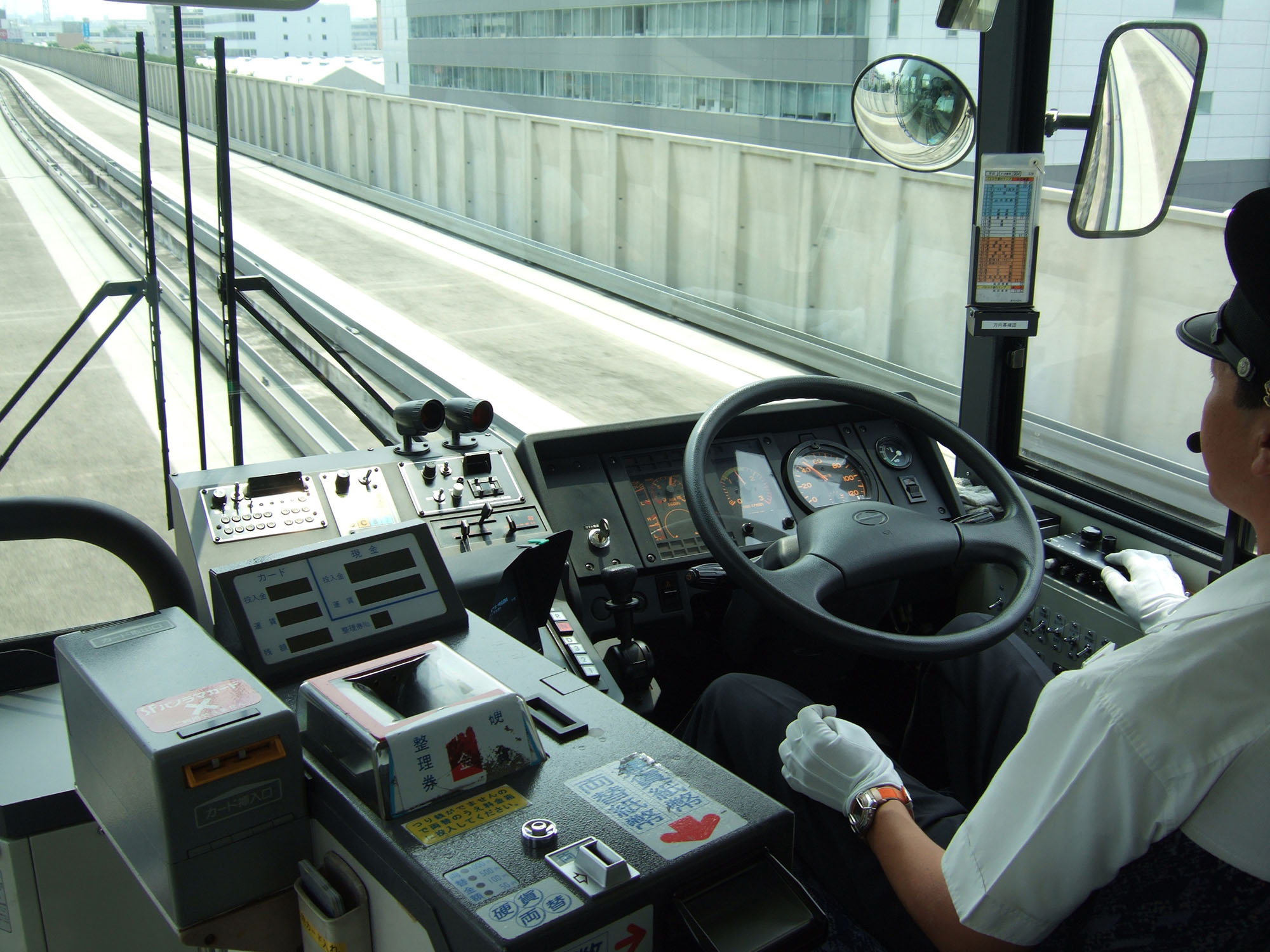
In operating a vehicle along a guided busway, the driver does not actually have to steer the vehicle. The guideways prevent any turning movements, and thus the vehicle can technically be operated “hands-free” (Figure 22.24). In some systems, such as Nagoya, Japan, there are safety concerns at the point the BRT vehicle leaves the guideway. If for some reason the driver does not re-engage physical steering, a mishap may occur. Thus, in the case of Nagoya, a forced stop is made at the exit from the guideway in order to remind the driver to use physical steering once again (Figure 22.25).
22.2.5Grade-Separated Busways
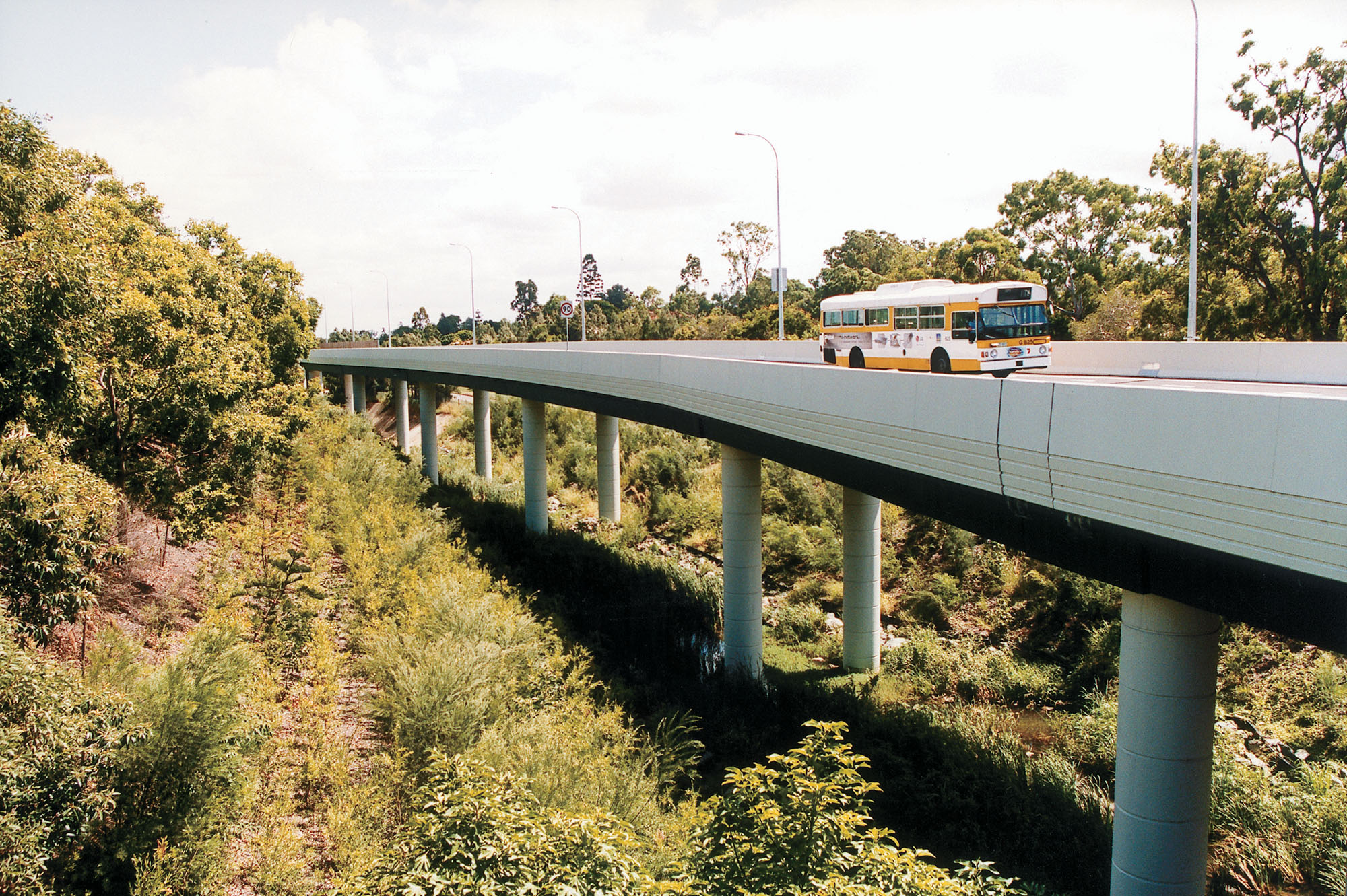
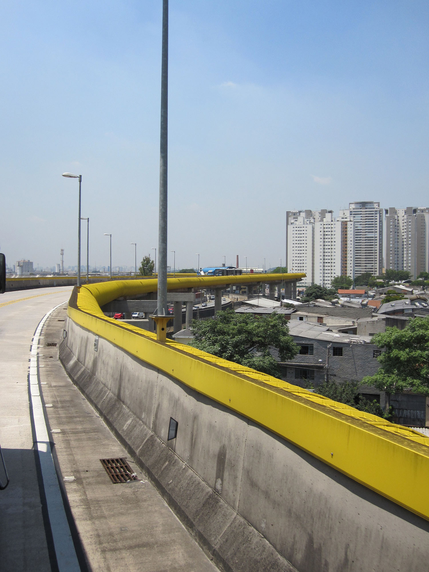
Grade separation, where the BRT corridor either runs on an elevated roadway or underground, is an option within narrow right-of-way configurations, as well as an option at very busy intersections and roundabouts. Grade separation can also be an option to consider bypassing difficult terrain or water (Figure 22.26). Because it is so expensive to build grade separations, it is usually done in strategic locations where the separation greatly improves operations. Grade-separated busways, however, can also be the length of a corridor, like Expresso Tiradentes in São Paulo, which runs on an elevated roadway. A grade-separated busway receives maximum points under the “Busway Alignment” metric of The BRT Standard, since it is a fully exclusive right-of-way, completely separated from mixed traffic.
In all cases, the physical terrain and base materials must be considered for their engineering appropriateness for tunnels or elevated structures. High water tables or hard bedrock can make underpasses and tunnels impractical from a cost and engineering standpoint. Likewise, soft soils can significantly increase the cost of securely siting pillars for elevated structures. Thus, an engineering and cost-feasibility analysis should be conducted whenever grade separation is being considered as an option along certain BRT corridor segments.
In addition to being highly costly (up to five times the cost of at-grade infrastructure), elevated busways can cause visual impacts in a community, and can also serve to split up an urban area.
22.2.6Transit Malls and Transit-Only Configurations
“Bus-only” or “transit-mall” corridors are effective options in giving complete priority to public transport. Such corridor segments are typically employed in central areas where space restrictions limit the ability to share space between both public transport and private vehicles, but can exist along an entire corridor, such as the Orange Line in Los Angeles, USA. Transit mall configurations receive maximum points under the “Busway Alignment” metric of The BRT Standard, since they constitute a fully exclusive right-of-way, completely separated from mixed traffic.
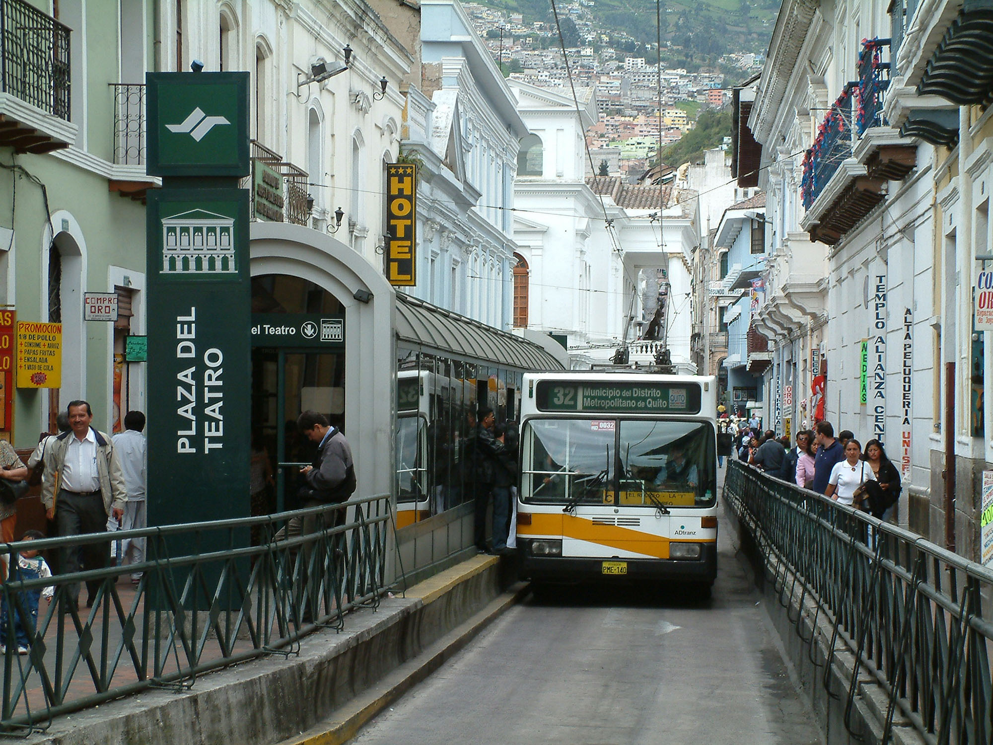
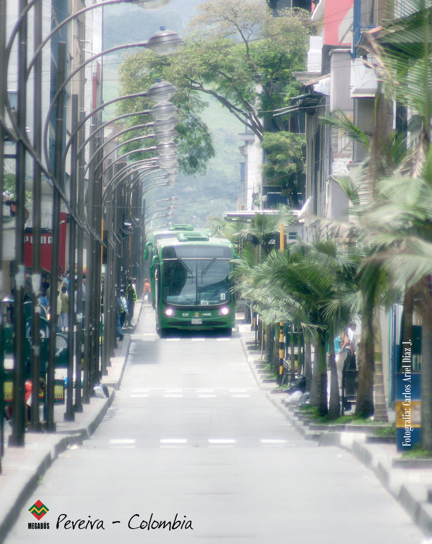
Transit malls are frequently an effective solution when a key corridor only has two lanes of road space available. Thus, segments with only seven meters of road space could be appropriate for a transit mall. Private cars, motorcycles, and trucks are banned either entirely from the corridor segment or during public transport operating hours. However, a one-way transit mall can operate on as little as three meters of space, as is the case with the Plaza del Teatro segment of the Quito Trolebús.
Transit malls are particularly appropriate when the public transport service enhances commercial activity and integrates well into the existing land-use patterns. In such cases, the transit mall creates a calmed street environment void of traffic congestion. Transit malls permit a maximum number of customers to access shops and street amenities. Thus, transit malls typically reside in locations where shop sales are quite robust. The lack of mixed traffic encourages an environment friendly to pedestrians and street activity.
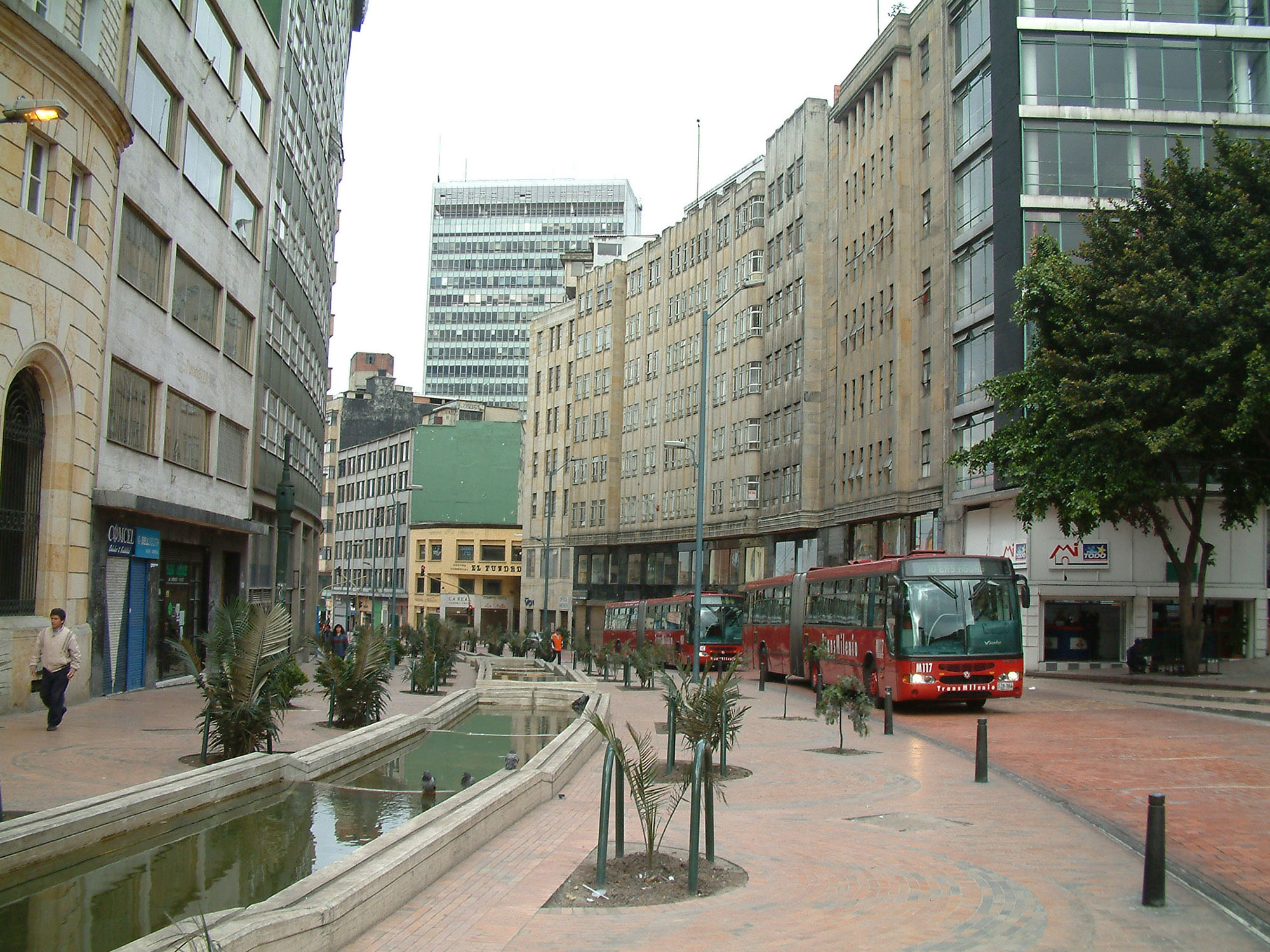
The open interaction between pedestrians and the public-transport service on a typical commercial transit mall requires that buses usually travel at slower speeds in these areas. Otherwise, accidents can occur, or the system will dampen the usefulness of the public space. However, the Plaza del Teatro segment of the Quito Trolebús avoids this problem by physically separating the pedestrian area from the busway. While this separation reduces the risk of accidents, it also makes the streetscape less socially inviting to pedestrians. Bogotá’s TransMilenio restricts maximum speed in its transit mall to 13 kph, while the rest of the system has a higher speed.
In instances where pedestrian movement along a transit mall is quite high, the presence of public-transport vehicles can become detrimental to the overall quality of the street. Conditions on the Oxford Street corridor in London have become difficult due to the fact that pedestrian volume exceeds the provided footpath space. In this case, the space given to public-transport vehicles (and taxis) may be better allocated entirely to pedestrians. Thus, at certain pedestrian volumes a street may be better utilized as a “pedestrian mall” rather than a “transit mall.”
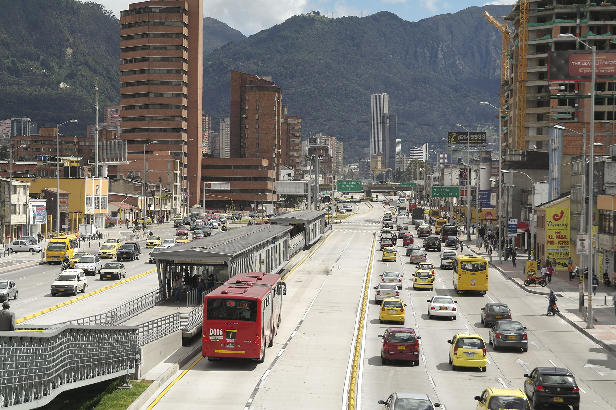
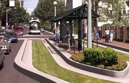
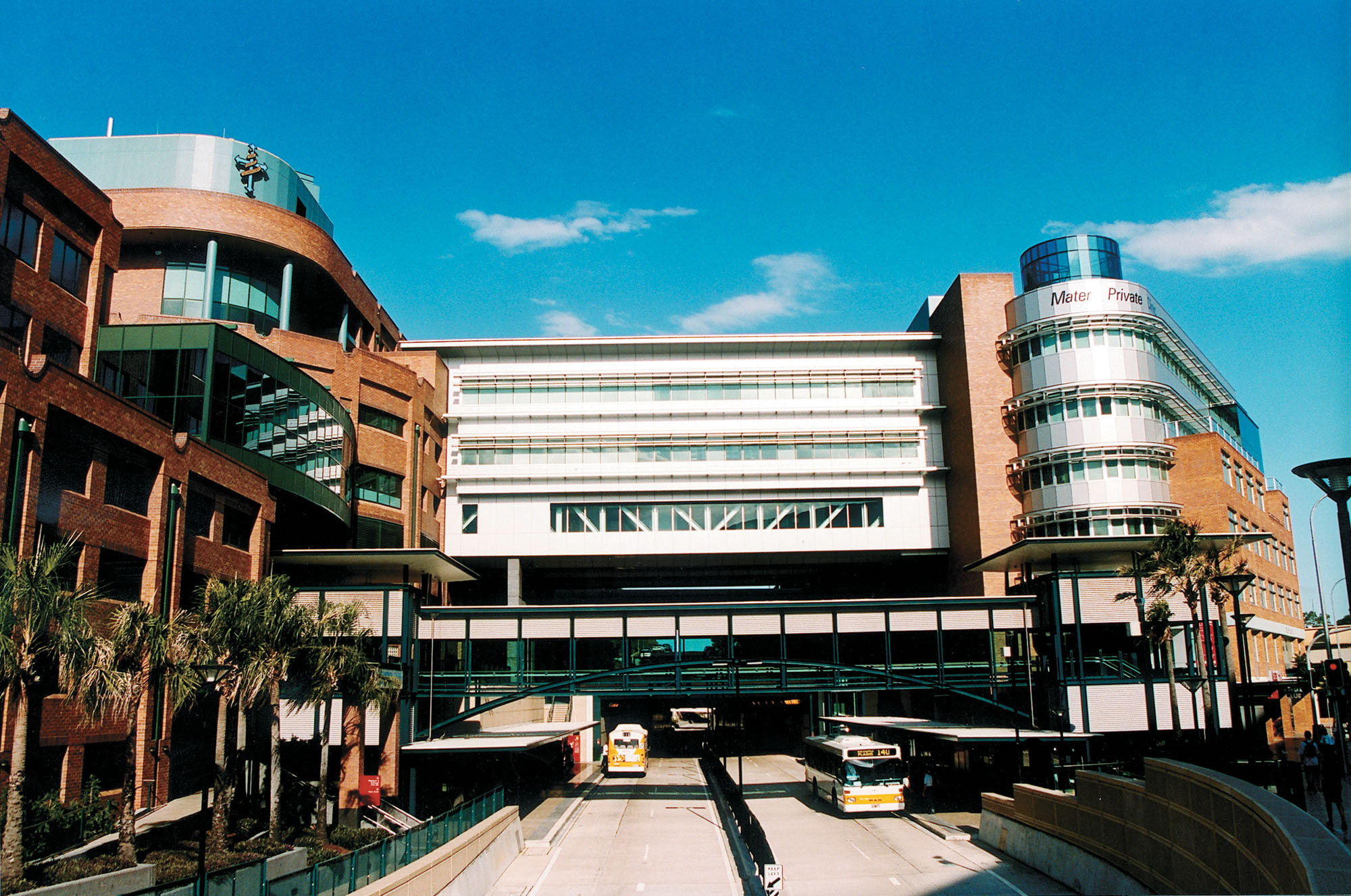
Cities such as Bogotá and Quito, employ bus-only corridors in selected locations. Likewise, Brisbane, Australia; Ottawa, Canada; and Pittsburgh, Pennsylvania, USA, also have developed bus-only corridors over certain roadway segments (Figure 22.28).
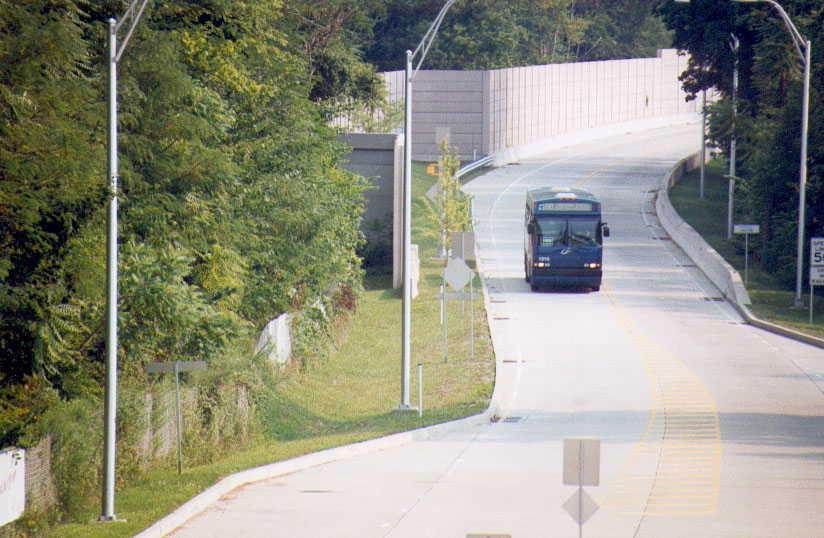
Transit-only corridors, though, are not just restricted to central business and shopping districts. For example, some busways are essentially limited-access roadways restricted to bus use. The West Busway in Pittsburgh, Pennsylvania, USA, moves through a bus-only corridor in largely residential areas (Figure 22.34). In the cases of Pittsburgh and Brisbane, the busways run along corridors with significant green space. Thus, there are no residential driveways entering directly onto the corridor. Otherwise, these schemes would likely be less viable.
Perhaps the greatest challenge in making transit malls and other transit-only corridors work is access for delivery vehicles and local residents. Some merchants desire round-the-clock delivery access, which is both a political and technical obstacle to implementing a transit mall. The loss of on-street parking and direct customer access by private vehicles may also be a worry for some merchants. In general, the experience to date has indicated that transit malls and pedestrian malls tend to both improve shop sales and property values. Thus, merchants sometimes object to vehicle restrictions at the outset
…they virtually never campaign for the abandonment of a scheme once it has come into operation. It is notable that, once a scheme has been put in place, traders are often the main people to voice a desire to extend its boundaries or period of operation.Hass-Klau 1992, 30
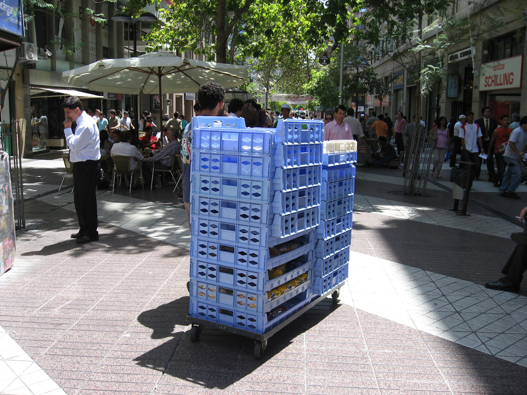
A common solution is to establish delivery access for shops during non-transit hours. Thus, merchants are able to move large goods during the late evening and early morning hours. Smaller goods can typically be delivered at any time by carts and delivery services operating from the pedestrian area (Figure 22.35). This may, however, pose a safety challenge for nighttime freight deliveries in some areas and should be addressed properly.
If the area is largely residential, then conflicts are usually with individuals seeking private-vehicle access to their properties and parking. Such conflicts can sometimes be resolved with the establishment of nearby parking garages and access during non-operating hours of the public transport system. In both the case of residential access and shop deliveries, the successful achievement of a transit mall is likely to require careful political negotiation.
22.2.7One-Way Pairs Configuration
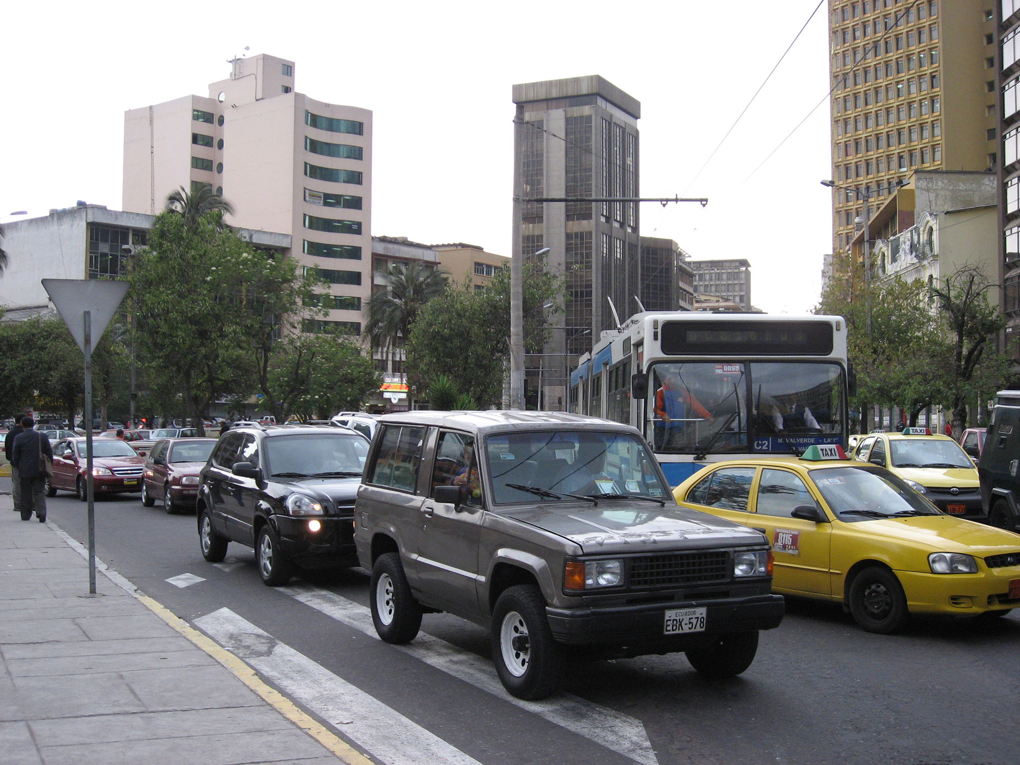
As an alternative to the transit mall, cities frequently consider splitting each direction of public transport service between two different (typically parallel) roads. The public transport system thus operates as two one-way pairs. This is sometimes called a couplet configuration. In this case, at least one lane of mixed traffic can typically be retained.
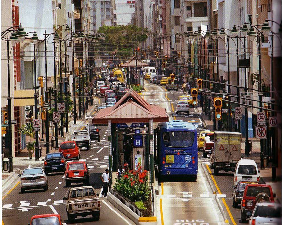
The chief advantage of splitting the route is the impact on mixed traffic, parking, and truck deliveries. Private vehicles retain some form of direct access to corridor properties. Also, this type of configuration often mirrors the existing bus routes, and thus is potentially more acceptable to existing operators. Guayaquil, Ecuador, has successfully utilized a split-route configuration in the central areas of the city (Figure 22.36) with the one-way pairs running in the center of the street. Johannesburg, South Africa, also has a similar configuration of median-aligned, one-way pairs in the downtown. Outside the denser city center, both directions of the BRT system are recombined in a more conventional two-directional configuration.
However, this configuration receives only half the amount of points under the “Busway Alignment” metric of The BRT Standard, because of the transfer penalty faced by customers if they need to transfer to a different line or go in a different direction and the potential for customer confusion in determining which station to board for which direction.
22.2.8Bi-directional One-Lane Configuration
In some special cases of lower demand and good technology, a short stretch of narrow busway could be operated with a single lane. Thus, a single lane would provide service to both directions on an alternating basis. To ensure that two vehicles do not try to use the one-lane segment at the same time, a special traffic control system is usually employed.
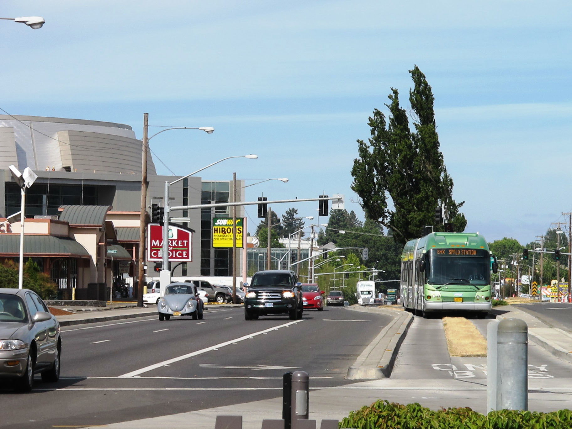
Single-lane operation is used most notably in Eugene, Oregon, USA (Figure 22.37). This option works because it is limited to short road segments and bus frequencies are low. An advanced signaling system holds oncoming buses and the busway breaks into two directions at key points for passing. Because of these low frequencies, Eugene’s Lane Transit District has been able to avoid most conflicts simply through scheduling.
Under such a design, as the length of the one-lane operation is increased, the greater the possible disruption to operation of the overall system. This option is also not likely to be viable in systems with high vehicle frequencies and high customer demand.
However, in some circumstances, single-lane operation can be used to overcome obstacles spanning short road segments. A single-lane tunnel or bridge or a narrow historic street may appear as insurmountable obstacles, and therefore cause planners to forgo an otherwise ideal corridor. Single-lane operation can be an option to consider in such situations.
22.2.9Virtual Busways
Similar to the bi-directional, one-lane configuration, a virtual busway is a single bus lane in the middle of a roadway used by both directions of travel. The difference is that the buses take turns in using the lane by direction and set by the need for queue jumping within the corridor. As the bus approaches the intersection, it will move into the virtual lane. The traffic light will have a separate public-transport vehicle phase allowing the BRT vehicles to leave the virtual lane, move into the general traffic lane, but before the rest of the traffic is allowed to go, so that the lane is relatively free-flowing. The bus proceeds in the general traffic lane until the virtual lane is once again dedicated to its direction of travel, usually upon approaching the intersection.
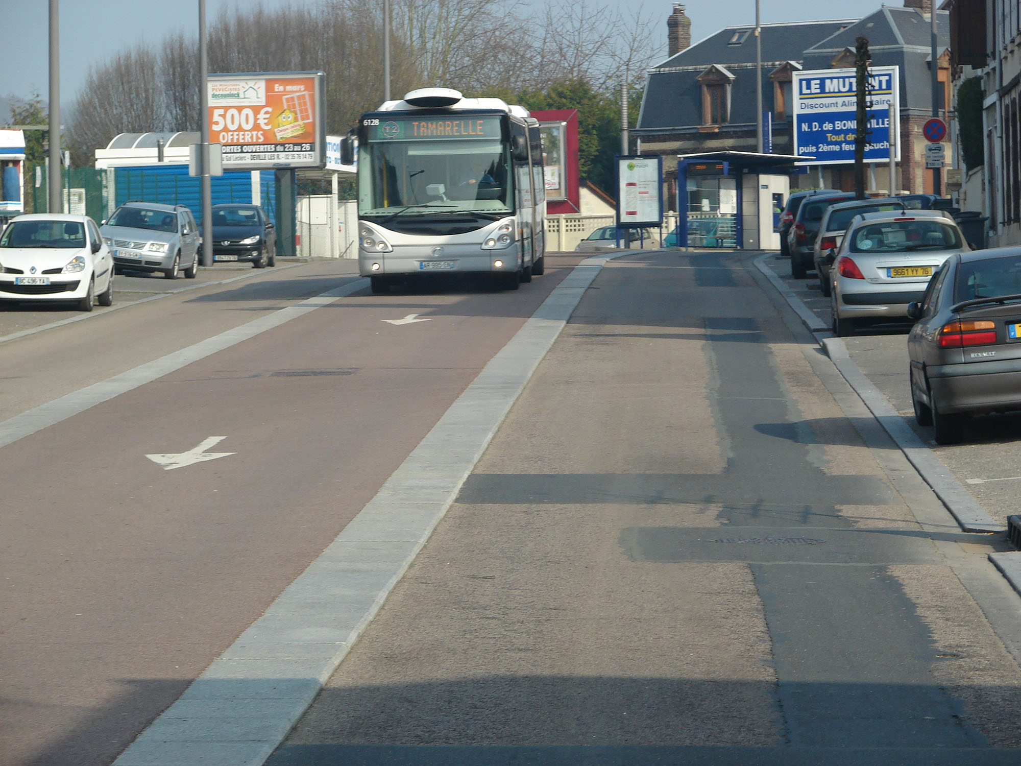
Rouen, France, has successfully implemented a virtual busway. The route has a three-lane cross section with on-street parking, catering to a general-traffic lane in each direction, and the virtual lane in the median. On the approach to each signalized intersection, the virtual lane is dedicated toward the intersection, thereby allowing the public-transport vehicle unimpeded access to the signalized intersection and a bypass or queue-jump lane. The stops are located prior to the signalized intersection stop line, by locating an island stop in the vicinity of the intersection (refer to Figure 22.37).
The degree to which the direction of dedication is allocated to each direction of travel along the corridor will be dependent on the levels of congestion (and queue backup) in the general traffic lanes during the peak periods of operation of the corridor.
Due to the location of these lanes in the median, as well as the limited width of roadway corridors, it may not be possible to protect these virtual lanes with delineators to ensure self-enforcement. The success of these lanes will therefore depend on a high degree of manual enforcement, which may increase operational costs. Additionally, virtual busways are generally most successful in relatively low-demand systems.
22.2.10Contra-Flow Busway
In addition to the different roadway configurations, system designers can opt for either “with flow” or “counter-flow” bus movements. “With flow” means that the vehicles operate in the same direction as the mixed traffic in the adjoining lanes. “Counter-flow” means that the vehicles operate in the opposite direction of mixed traffic. “Counter-flow” is sometimes used if the doorways on the existing buses require the bus to drive on a certain side. Counter-flow bus lanes are used in various conventional bus systems around the world (Figure 22.40). Often, counter-flow designs are employed to discourage private vehicles from entering the bus lane. However, the counter-flow lane may simply result in busway congestion if private vehicles nevertheless decide to enter the area.
“Counter-flow” set-ups do have a potentially serious problem with increased pedestrian accidents. Pedestrians can be unaccustomed to looking in the direction of the counter-flow lane, and thus cross unknowingly into a dangerous situation.
Counter-flow systems are generally not employed in BRT systems, particularly due to concerns over pedestrian safety. Quito briefly utilized counter-flow movements for its Ecovía corridor since its only available vehicles possessed doorways on the wrong side. However, once the new vehicles arrived from the manufacturer, Quito converted the corridor back to “with flow” movements.
22.2.11Mixed-Traffic Operation
A BRT system can operate in mixed traffic for certain segments of a corridor. If the corridor is not congested and future congestion can be controlled, it may make sense not to have dedicated infrastructure at that point. Many cities are also designing “direct service” systems where services, by design, travel both on the trunk infrastructure in dedicated lanes and off the trunk corridor, often in mixed traffic. Direct-service systems can be found in Pittsburgh, Pennsylvania, USA; Guangzhou, Lanzhou, and Changzhou, China; Ottawa, Canada; Cleveland, Ohio, USA; and a growing number of cities around the world.
Many systems, however, operate in mixed traffic at precisely the areas where dedicated infrastructure is needed, that is, downtowns where there may be a lot of congestion. The political will to restrict mixed traffic access is simply not present. If the link is congested, then this choice will have a detrimental impact on travel times, system control, and the overall system image. Therefore, mixed-traffic operation is awarded 0 points under the “Busway Alignment” metric in The BRT Standard.
Near the Usme terminal of the Bogotá TransMilenio system, the BRT vehicles operate in mixed-traffic lanes. This design choice is due to two factors: (1) Limited road space (two lanes in each direction) and limited right of way; (2) Relatively light mixed-traffic levels. Since the Usme terminal area does not see high congestion levels, the BRT system co-exists with the mixed traffic in a way that does little to affect public transport operations. In this case, the mixed-traffic operation has a negligible impact on system performance. However, mixed traffic may result in higher bus conflicts with other road users, and experience has indicated that, in particular, bus-motorcycle accidents are more prevalent.
By contrast in Changzhou, China the BRT corridor passes through a mixed-traffic section in the city center. This, combined with multiple four-phase intersections, has a major negative impact on BRT speeds.
Mixed-traffic operation can also become necessary when a BRT vehicle must traverse around a flyover or other obstacle. As the BRT vehicle moves to the center median, it must temporarily mix with cars descending from the flyover. While this set of circumstances is undesirable from a travel-time and system-control standpoint, the congestion usually does not occur at the bottleneck or flyover, but prior to it. Providing public transport vehicles with separated facilities up to the flyover will allow them to jump the queue with little detriment to overall travel time.
Thus, short and selected points of mixed-traffic operation can likely be tolerated without undermining the functionality of the entire system. However, longer periods of mixed-traffic operation can render the BRT system indistinguishable from a standard bus system. The impact of such a design is not just on the performance and operational control, but also on the psychological image of the system. The exclusive, priority lane given to a BRT vehicle is the principal physical feature that sets it apart as a higher-quality form of transport. The segregated lane is what allows customers to develop a “mental map” of the system in their minds. Removing this segregation from significant portions of the system greatly diminishes the metro-like nature of BRT, and makes it far less attractive to discretionary riders.
An option for mixed-traffic operations is to include queue-jump lanes, which help give some form of priority during peak periods to avoid vehicles being trapped in congestion.
Queue-jump lanes can be located on the curbside or in the middle of the corridor (Figures 22.42 and 22.43). Issues that affect the location of these lanes are: driveway spacing and frequency, the presence of a median, median break, turn lanes, etc. Issues associated with queue-jump lanes are the difficulty with encroachment by general traffic vehicles, and difficulty with enforcement due to the need to cross the dedicated lane to access driveways, turn lanes, and median breaks.
In some instances, access to the queue-jump lanes by general traffic is only restricted during peak periods, that is, general traffic may utilize these lanes during the out-of–peak periods. This weakens the exclusivity of the road space, which in turn leads to higher rates of peak-period violations, and hence should not be encouraged.