25.2Basic Concepts
Almost always, great new ideas don’t emerge from within a single person or function, but at the intersection of functions or people that have never met before.Clayton M. Christensen, author, 1952–
A station typically has the following standardized components:
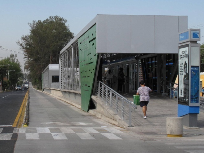
- Access and arrival areas: is where people access the station (ramp, stairs, elevators), ideally at grade from a crosswalk, but can also include from a bridge or tunnel. This is how the station integrates into the urban environment.
- Entrance areas: are the areas that are not directly spaces for boarding and alighting but can include kiosks for buying tickets, seating areas, etc. These are areas where passengers can find information about the system. This area can be demarcated with fare gates or turnstiles where customers enter the system; and
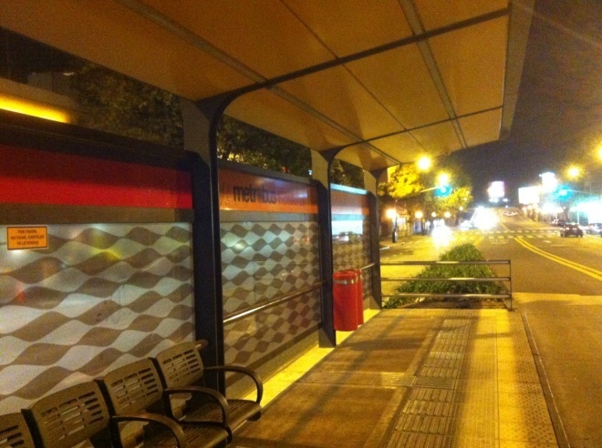
- Platform: this is the main area where passengers wait to board and to where they alight. Circulation space and waiting space will need to be planned for, as well system information and wayfinding. This is also where the bus pulls up to the station.
Station platforms can also be described as sub-stops with docking bays for the buses.
- Docking bays: this is where the bus pulls up to in order to let passengers on and off – the platform – vehicle interface. It may have doors, platform extenders, and/or guide rails. Typically there are two docking bays per sub-stop. The docking bay must be long enough so that all the doors of the bus (including articulated busses) can open simultaneously. ; and
- Sub-stops: also known as station subdivisions or modules. A station may be composed of one or multiple sub-stops. Typically sub-stops are organized so that busses can pass each other while docked at a station. A sub-stop should have passenger information, wayfinding, and seating (or perching in constrained locations). Usually a sub-stop will have two docking bays per direction. . If more docking bays are needed due to demand, another sub-stop should be added. Thus, passing lanes are also part of the station footprint to be considered.
BRT stations also serve different purposes, that affect design, including size of the station:
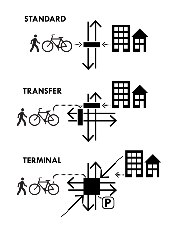
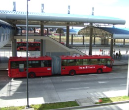
- Standard - typical station along BRT corridor. It is the workhorse of the system, and by virtue of repetition, it often becomes the symbol of the system. The macro-location will be determined by the operations plan. The exact location will be determined by a site analysis with pedestrian access as the foremost concern.
- Transfer - stations where transfers occur between BRT lines, feeder (non-BRT) bus routes, and/or other transit modes (LRT, taxi, pedicab). The typical defining characteristic is that the transfers occur within a defined, controlled space, where the services are co-located or linked.
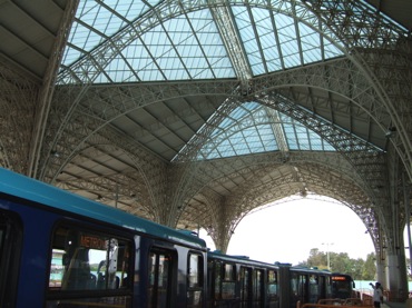
- Terminal - larger facility typically located at the end of a BRT line or in important destinations. They are usually considered anchors of the system. They serve as interchange points between various modes and will become important destinations in their own right. Hence, there are opportunities to construct a significant building, similar to city’s main train station or airport. Space is can be made available for busses to park (layover) for driver breaks, minor servicing, and schedule adjustments.
One key difference between systems and conventional bus systems is the nature of the transfer between different routes and services. Within a system, all trip service and routing options are integrated both in terms of fare structure and physical proximity or preferably do not require a transfer at all.
Systems employing direct services will likely not utilise either intermediate transfer stations or terminals. Instead, vehicles operating in a direct services system will proceed directly from trunk corridors into lower-density areas.
Feeder connections to the trunk lines do not necessarily occur only at major terminal facilities. Feeders can also intersect the trunk corridors at what are known as intermediate transfer stations. These stations are a hybrid facility between ordinary local stations and terminal facilities.
The options for facilitating transfers can be divided into open transfers and closed transfers. As the name implies, an open transfer takes place in an open environment in which it is not necessary to physically combine the feeder and trunk sub-stops into an enclosed environment. By contrast, a closed transfer takes place in a fare-controlled environment.
There are several options for facilitating transfers between corridors. These options include:
- Platform transfers: the most desirable for the customer, because it is easiest – to transfer from one service to another is just a walk across or along a platform.
- Underground tunnels / overhead pedestrian bridges: In some instances, it may be necessary to for transfers to take place by customers walking from one corridor to another. To maintain a “closed” environment with paid customers only, a segregated tunnel or pedestrian bridge is required; and
- Interchange facility (multi-bay or multi-story facility): when different services are located in the same space, but at different levels. These facilities often take a lot of space.