25.6Station Dimensions
I refuse to accept other people’s ideas of happiness for me. As if there’s a ‘one-size fits all’ standard for happiness.Kanye West, musician, 1977–
Station length and width have minimuns to work well; the influential factors are discussed in the following sections but in order to create proper circulation and wait area, one may compensate for the other, as usually right-of-way is an imposing restriction.
25.6.1Station Length
In order for multiple sub-stops to function properly, vehicles must be able to overtake buses stopped at sub-stops. In general, the absolute minimum distance required for one vehicle to pass another is one-half the bus length. For example, an 18-meter articulated vehicle requires at least nine meters of separation between docking bays. This minimum distance should only be used at stations with fairly low frequency, or where right of way constraint is a significant issue. Normally, systems require more space because:
- Entering and exiting docking bays with such limited space increases the time it takes to pull into the docking bay, which reduces speeds and adds to saturation levels;
- If a vehicle using the same docking bay is directly behind another, the waiting vehicle should be able to wait behind the first vehicle without blocking the docking bay behind it.
Based upon this criteria, the minimum spacing should be approximately 1.7 times the length of the vehicle. In the case of an 18-meter articulated vehicle, this distance would be approximately 30 metres.
If the vehicle to platform interface does not utilise a boarding bridge, then greater precision is required to align the vehicle to the platform.
As stated in Chapter 7, section 7.6, while boarding bridges allow buses greater room for error in docking to the station and allow passengers greater confidence when boarding and alighting, there are a few disadvantages. The added cost of the boarding plate and the pneumatic system to operate it entails a modest increase in vehicle costs, as well as an increase in maintenance costs. As a moving part, the boarding bridge also introduces additional maintenance issues and the potential for malfunction. The deployment of the bridge itself takes about 1.5 seconds. Likewise, the retrieval of the boarding bridge at departure also requires about 1.5 seconds. While this deployment and retrieval roughly coincide with the opening and closing of the doors, they introduce a slight delay to the boarding and alighting process.
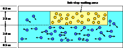
Unless saturation is very low, room should be left for a second vehicle to stop at each sub-stop, both to avoid queues interfering with the operation of the adjacent sub-stop and also to help disperse waiting passengers within the sub-stop. Generally, it is optimal to provide two boarding and alighting spaces, though in a few exceptional circumstances three queuing spaces maybe be optimal. Table 25.2 outlines the conditions favouring one or two bus docking bays.
Table 25.2Sub-stops and queuing spaces required
| Saturation level (X) From | Saturation level (X) To | No. of sub-stops | No. of lanes | Bus docking bays (vehicle lengths) | Extra queuing positions (vehicle lengths) | Total station length (metres) |
|---|---|---|---|---|---|---|
| 0 | 20% | 1 | 1 | 1 | 0 | 19 |
| 20 | 40% | 1 | 1 | 2 | 0 | 19 |
| 40% | 70% | 2 | 2 | 2 | 0 | 104 |
| 70% | 80% | 2 | 2 | 2 | 1 | 142 |
| 80% | 100% | 3 | 2 | 2 | 0 | 156 |
| 100% | 140% | 4 | 2 | 2 | 0 | 208 |
| 140% | 180% | 5 | 2 | 2 | 0 | 260 |
| 180% | 200% | 5 | 2 | 2 | 1 | 355 |
Notes:
- Saturation refers to the percentage of time that the station is occupied by BRT buses entering the stopping area, opening doors, passengers boarding and alighting, doors closing, and leaving the stopping area.
- The total station length is based on 18m BRT buses. 12m or smaller buses will be correspondingly smaller
- Total length = (19 m number of docking bays) + 33 m 19 m = space for extra vehicle in queue33 m = 19 m + 14 m (space for docking bay + passing distance)Station length excludes fare collection, typically 10 meters per entrance
As can be seen in Table 25.2, multiple sub-stops add considerable overall length to a station.
Box 25.1 TransMilenio stations
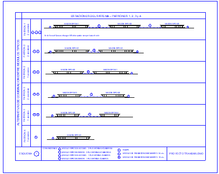
198 metres (3 sub-stops, 5 docking bays)
124 metres (2 sub-stops, 4 docking bays)
112 metres (2 sub-stops, 4 docking bays)
94 metres (2 sub-stops, 2 docking bays)
53 metres (1 sub-stop, 2 docking bays)
62 metres (1 sub-stop, 2 docking bays)
25.6.2Station Width
for passengers to enter and exit the area, and enough space for the infrastructure itself. If length is determined, and access is made by the extremes of the stations, which is a good idea for easy of access, one must leave a width for circulation and a with for the waiting area, lateral infrastructure may demand some width as well.
- People avoid walking too close to walls, fences and the curb. Thus a 0.3-0.5 meter shy distance is included in any width calculation.
This reasonaing can be transformed in the following formulas (the concepts of vehicles flow on chapter 24 may assist).
Equation 1: Calculation of platform width
\[ W_p = W_i + W_u + W_c + W_{opp} \]
Where:
- \( W_p \): Total platform width;
- \( W_i \): Width required for basic station infrastructure, usually equal to 1 meter
- \( W_u \): Width required for waiting passengers in one direction;
- \( W_c \): Width required for circulating passengers;
- \(W_opp \): Width required for passengers waiting for vehicles going in the other direction (value = 0 when the station serve only one direction or are staggered);
Equation 2: Width required for circulating passengers
\[ W_c = {\text{Flow}_\text{pax} \over \text{saturationflowperwidthunit}} \]
Where:
- \( W_c \): Width required for circulating passengers;
- \( \text{Flow}_\text{pax} \): Number of circulating passengers expected per hour using peak hour numbers.
- \( \text{saturationflowperwidthunit}\): Number of pedestrians that can walk along a unit of width (for instance, 1 meter) path per hour and still provide a reasonable level of service. Usually 2,000 pedestrians crossing a meter wide section in one hour is used as the basis for determining width needed for circulating passengers.
Equation 3: Area required for waiting passengers
\[ S_u = {Q_{u\text{pax}} \over Dw_\text{max}} \]
\[ S_{opp} = {Q_{opp\text{pax}} \over Dw_\text{max}} \]
Where:
- \( S_u\) and \(S_{opp} \): Minimum area required for waiting passengers. This is a function of the maximum number of passengers projected to queue divided by the capacity of an area (for instance, a square meter) to hold waiting passengers.
- \( Q_{u\text{pax}} \): Maximum number of passengers projected to queue in one direction of a substop;
- \( Q_{opp\text{pax}} \): Maximum number of passengers projected to queue in opposite direction of a substop;
- \( Dw_\text{max} \) Acceptable number of passengers waiting per area unit (the maximum is 3 people per square meter).
Equation 4: Width required for waiting passengers
\[ W_{opp} = {S_{opp} \over L_{opp}} \]
\[ W_{u} = {S_{u} \over L_{u}} \]
Where:
- \( S_u\) and \(S_{opp} \): Minimum area required for waiting passengers
- \( L_u\) and \(L_{opp} \): Platform lenght (usually corresponding to the extension of the vehicle on the outside plus length the vehicle has to maneuver. It can be longer if required in narrow stations, by increasing distannce between platformas, but if much longer will require operators to organize the queues in peak hours.
- \( S_u\) and \(_{opp} \): Minimum width required for the area of waiting passengers in the platform. It’s calculation derives from area formula \( S = L * W \)
Equation 5: Estimate of total boarding passengers at a sub-stop
\[ Q_\text{pax} = \sum_{i=1}^{N_\text{routes}}{Pb_i \over F_i} = \sum_{i=1}^{N_\text{routes}} {pbv_i} \]
Where:
- \( Q_\text{pax} \): Maximum passenger queue expected; represents the sum of all boarding passengers in the given direction, i.e. how many passenger will board the bus is when it gets to the station (this is used for calculating \( Q_u \) and \( Q_p \) above).
- \( Pb_i \): Passengers boarding on BRT route i (per hour. during peak);
- \( F_i \): Frequency of line i (BRT vehicles per hour, during peak);
- \( pbv_i \): Average number of passengers boarding per BRT line i vehicle (during peak)
Box 25.2 Example of station width requirement calculation
A simplified application of this formulas, would be as follows, assuming an off-set station, given:
- station infrastructure consumes 0.5 meters on each side for a total of 1 meter
- waiting areas for the two directions are offset (\(W_opp = 0\))
- 18m long BRT vehicle (\(L = 18m\))
- 4 routes will stop at this platform, serving 1000 passenger altogether in the peak (\(\sum Pb_i = 1000 \)) in a balanced way
- Each route has a headway of 12 minutes, which means in average one vehicle arriving every 3 minutes, or 20 vehicles/hour at the platform.
- number of passengers expected to cross this platform in the peak to reach exit or other platforms is 4,000/hour
If we assume boarding passengers arrive at a constant rate at the platform, and the proportion of passengers boarding in each route being similar, as proposed:
- each route would have 250 pax/hour
- with one vehicle every 12 minutes there are 5 vehicles arriving per hour
- in average 50 passengers would board each vehicle of each route
- if all 4 routes arrive close to each other, 200 people might add up waiting to borad the vehicles (\( Qp_U=200\))
\[ Q_\text{pax} = \sum_{i=1}^{N_\text{routes}}{Pb_i \over F_i} = \sum_{i=1}^{N_\text{routes}} {pbv_i} \]
\[ Q_\text{pax} = {250 \over 5} + {250 \over 5} + {250 \over 5}+{250 \over 5} = 200 \]
200 waiting passengers divided by 3 the maximum accepted occupancy of space: three passengers per square meter (\( Dw_max = 3 pax/m^2 \)) implies 66.6 square meters are required as waiting area.
\[ S _u = {Q_u\text{pax} \over Dw_\text{max}} \]
\[ S_u = {200 pax \over 3 pax/m^2} = 66.6 m^2 \]
The BRT vehicle is 18 meters long, if we consider 2 extra meter of lenght for the internal side of the station, corresponding to the space a BRT vehicle uses outside: To total 66.6m2 in 20 m of extention, the waiting area needs to be 3.33 8m wide (Wu = 3.33m).
\[ W_{u} = {S_{u} \over L_{u}} \]
\[ 3.33 {66_{u} \over 20_{u}} \]
The width for circulation of passengers coming and going from and to other platforms will be 2 meters
\[ W_c = {\text{Flow}_\text{pax} \over \text{basicpax saturationflowperwidthunit}} \]
\[ W_c = {4000 \over 2000} = 2m \]
And finally to total width of the station results in 6.33 metres.
\[ W_p = W_i + W_u + W_c + W_opp \]
\[ 1m + 3.33m + 2m + 0m = 6.33m \text{; add}\ 0.5m\ \text{shy distance} = 6.83m \]
Round up to 7.0m
25.6.3Station Height
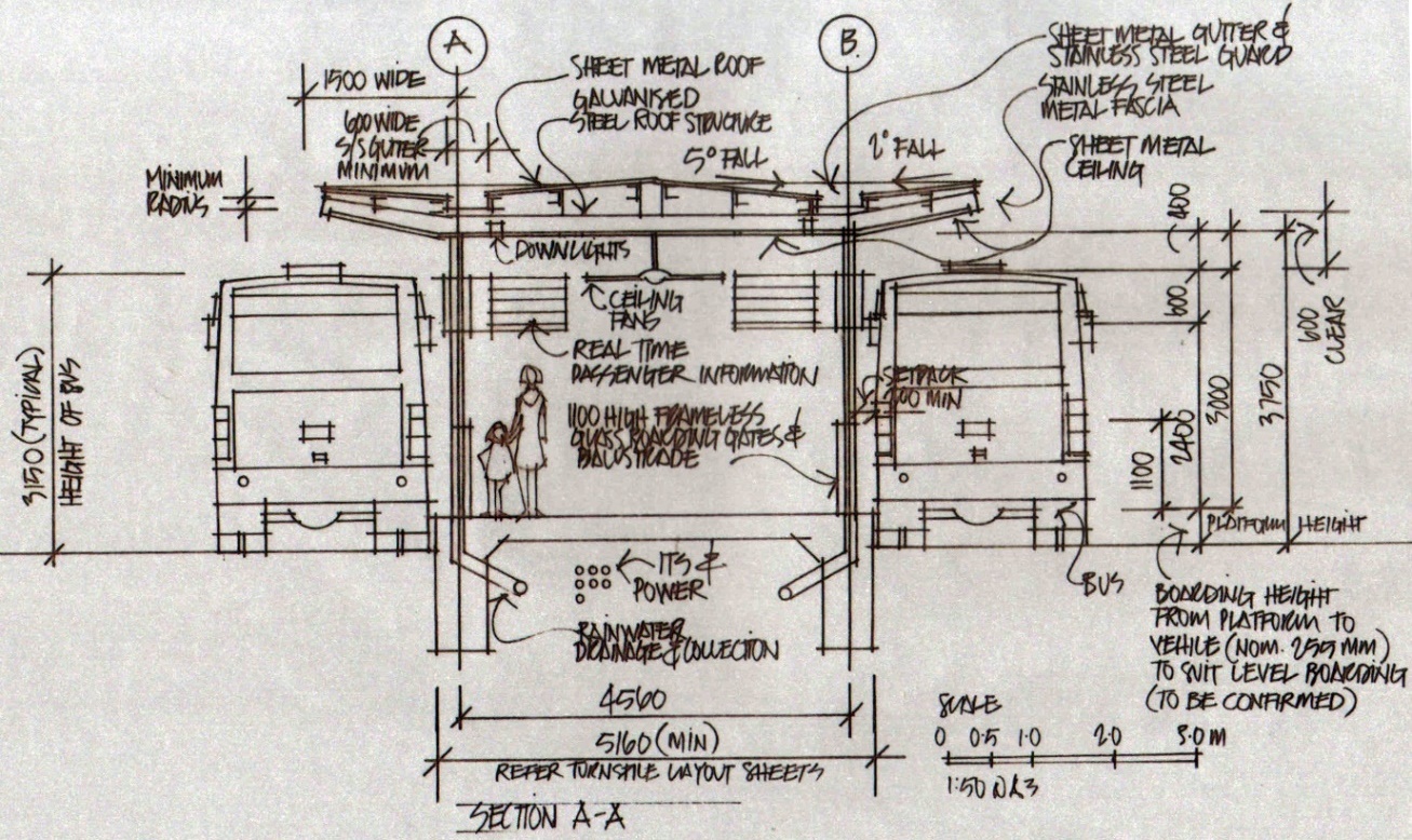
Station height from floor to ceiling should be at least 3.5m in a partially enclosed station, and at least 4m in a fully enclosed station. Beyond these minimum dimensions, station heights can vary according to the particular design. An example of BRT station dimensions provided by architect Derek Trusler with ITDP for a study in Malaysia is provided in Figure 25.55.
25.6.4Station and Road Cross-sections
Station and road cross-sections will vary according to the conditions of each urban corridor and the demand and operational characteristics of the system. However, the following general guidelines can be applied:
- BRT stations can be as narrow as 4 meters but should preferably be at least 5 meters wide, and preferably at least 6m wide where passengers are boarding and alighting on both sides of the platform.
- Space is often most constrained at the station area. Since the station area is the critical point for BRT operation, this may mean that other modes are partially “sacrificed” in order to allow for excellent BRT operation. Mixed traffic lanes can be as narrow as 2.8 meters at the station area. Walkways can be narrowed to 2 meters or even 1.5 meters (if the walkway is unobstructed). Bike lanes can be narrowed to 1.5 meters or even 1 meter in low volume locations.
- Where the BRT has passing lanes, the stopping lane can be narrowed to 3 meters if necessary.
ITDP’s station section for Wangzhougang Station in Yichang, illustrated in Figure 25.57, is an example of the need to reduce the width of non-BRT lanes at the BRT station in order to retain in this case a minimum 5-meter BRT station width. Between stations, where space is less constrained, mixed traffic lanes are 3.5 meter, the bike lane 1.5 meter (plus a 0.5-meter divider), and the walkway 3.5 meter. At the station the mixed traffic lanes are reduced to 3.2 meter, the bike lane to 1 meter (without a divider), and the walkway to 3 meter. Yichang is a high-capacity BRT system. Reducing space for pedestrians should be the last resort as with customers going to and from the station, pedestrian traffic may be higher in these station areas.
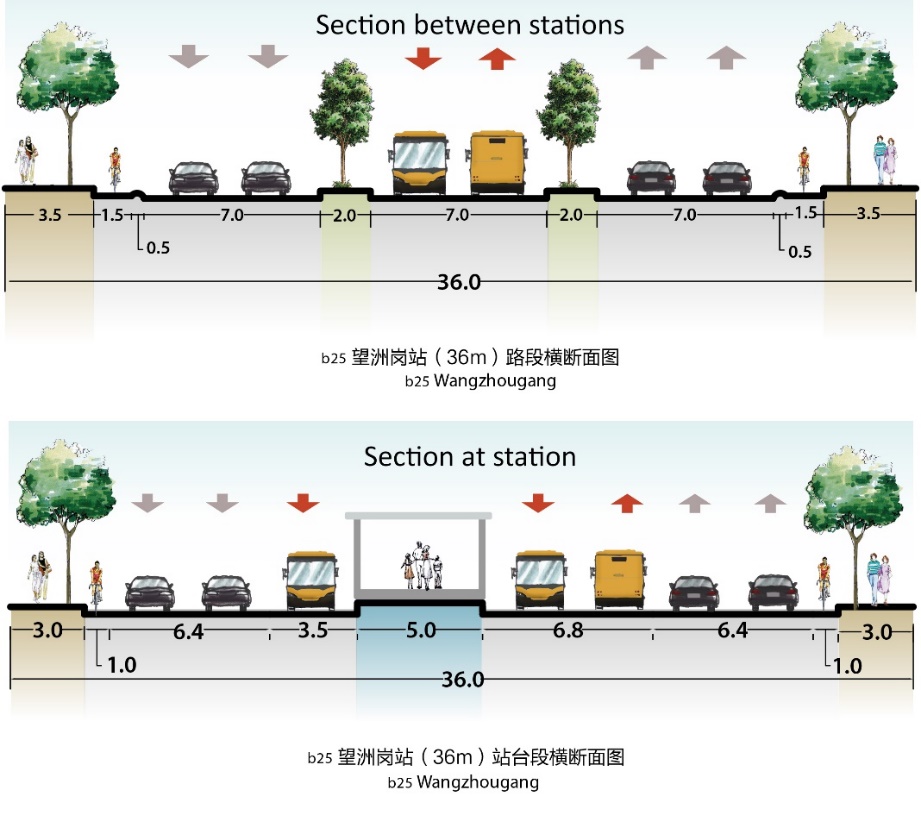
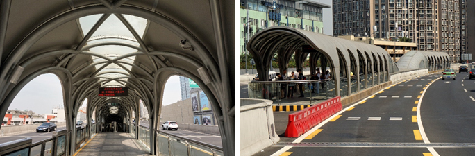
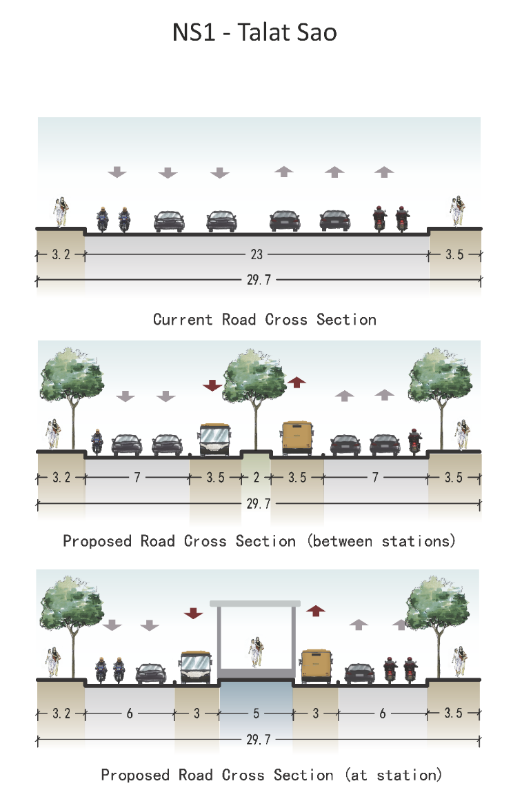
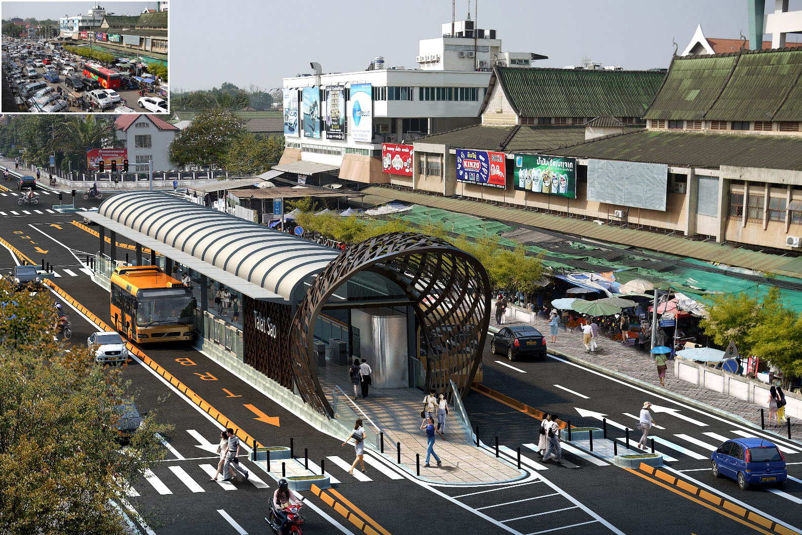
Figure 27,58 provides an example of a cross-section for a medium capacity BRT system: the design in Vientiane, Lao PDR. Note that in the proposed cross-section between stations, mixed traffic has 7 meter of space per direction, which at the BRT station is reduced to 6 meter. Since BRT vehicles are stopping on both sides of the platform, the BRT lane width is also reduced to 3 meter at the station. A rendering of the same station is provided in Figure 25.59.
The following table lists typical cross section widths at BRT stations. It is organized from the outside-in (from the building line to the center line). Priority is shown for each element. Use the prioritization scheme to guide the assemblage of the cross-section.
Table 25.3Typical elements in a cross-section at a BRT station
| – | Pedestrian Zone | 2 - 5.0m |
|
|---|---|---|---|
| 1 | Paved Accessible Pedestrian Route | 2 - 3.0m |
|
| 3 | Bicycle parking | 2.0m |
|
| 2 | Trees and landscaping | 1.0m or wider |
|
| 3 | Pedestrian-bicycle buffer | 0.0 - 1.0m |
|
| 2 | Bicycle lane | 1.5 - 5.0m |
|
| 3 | Bicycle-auto buffer | 0.3 - 1.5m |
|
| – | Auto parking | n/a |
|
| 4 | Auto lane | 2.7 - 3.3m |
|
| – | Auto turn lane | n/a |
|
| – | Auto lane shoulder | n/a |
|
| 2 | Auto-BRT buffer | 0.2 - 0.5m |
|
| 2 | BRT passing lane | 3.5m |
|
| 1 | BRT lane | 3.0 - 3.5m |
|
| 1 | BRT station | 5.0 - 10.0m |
|