26.4Design Layout
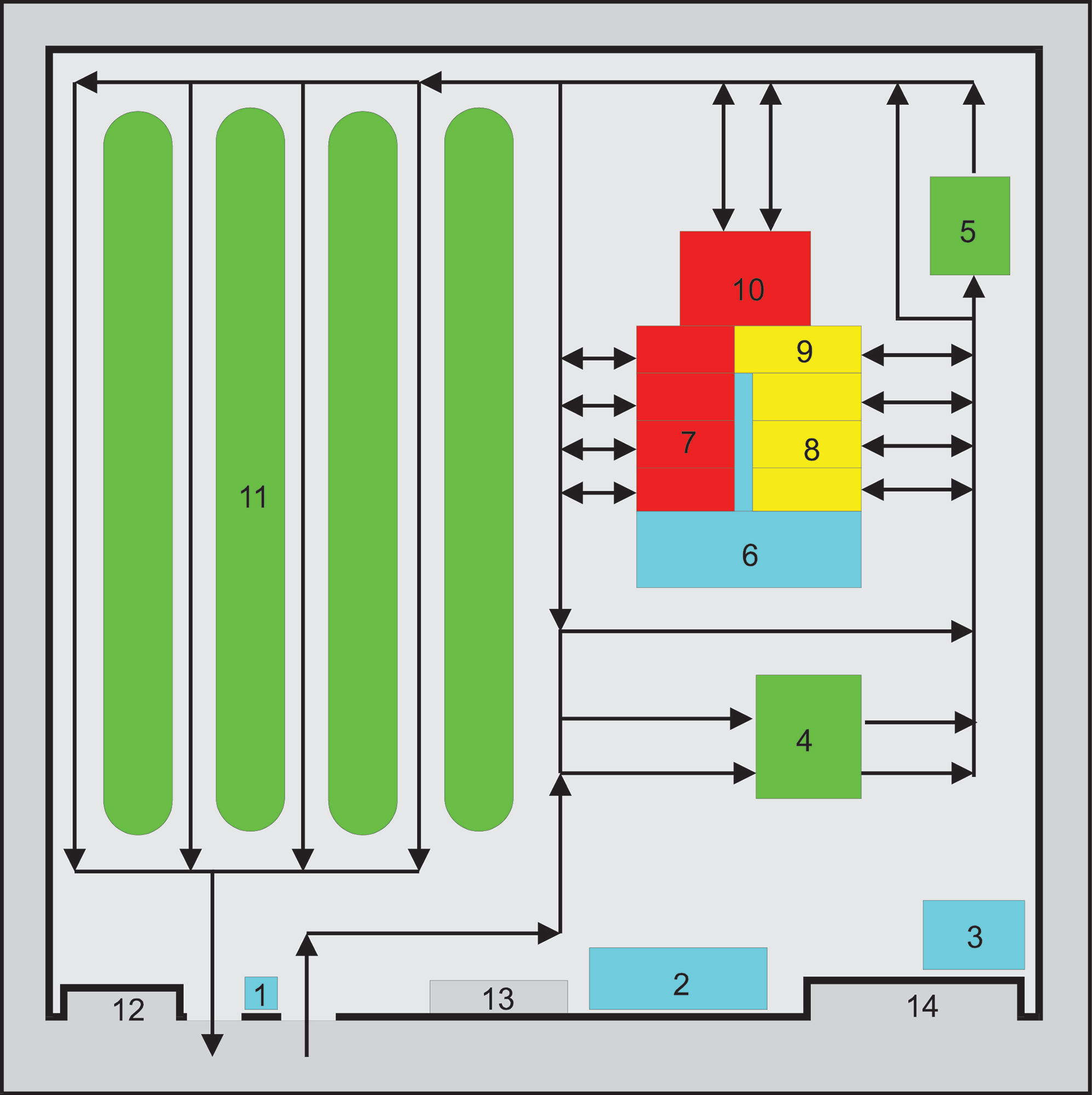
The internal design of the depot area should allow for a logical movement of vehicles based on their typical requirements. Figure 26.3 shows a typical layout for a depot area. This layout is for countries that drive on the right-hand side of the road, hence allowing for an anticlockwise movement of travel for the vehicles and minimizing vehicle conflicts inside the depot. For countries that drive on the left, the circulation should be in a clockwise direction to obtain the same benefit.
Table 26.2Legend for Figure 26.3
| Legend | Description |
|---|---|
| 1 | Gate and visual inspection area |
| 2, 3, 6 | Administrative offices for the concessioned operators |
| 4 | Refueling area |
| 5 | Vehicle washing and cleaning area |
| 7, 10 | Major repairs |
| 8, 9 | Minor repairs and maintenance |
| 11 | BRT vehicle parking |
| 12 | Private vehicle parking |
| Green | Operational vehicles |
| Yellow | Vehicles requiring minor or routine maintenance |
| Red | Vehicles requiring major repairs |
The following expressions hold:
Area occupied by a vehicle, VA:
- Articulated bus: 45 m2
- 12 m long bus: 30 m2
- 10 m long bus: 25 m2
- Access area \(\text{AP} = (2.5 \text{ to } 4.0)\,\text{VA}\)
- Area for visual inspection, fueling, and cleaning \(\text{VI} = (6.0 \text{ to } 8.0)\,\text{VA}\)
- Parking area \(\text{PAR} = 2\cdot\text{VA}\cdot{}N\), where \(N\) is the number of vehicles
- Maintenance area \(\text{MA} = 0.2\;\text{PAR}\)
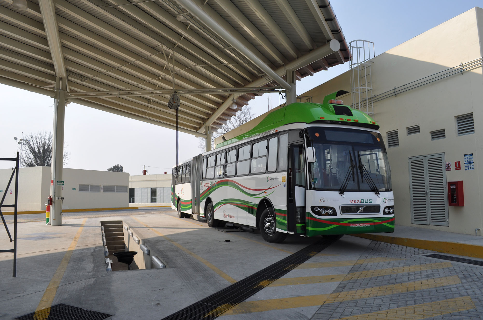
Vehicles will enter the depot area as they are instructed to temporarily come out of service by the control center. As BRT vehicles enter the depot, they are visually inspected at point 1 in Figure 26.3. The vehicle is classified as “green” (operational), “yellow” (in need of minor repairs), or “red” (in need of major repairs).
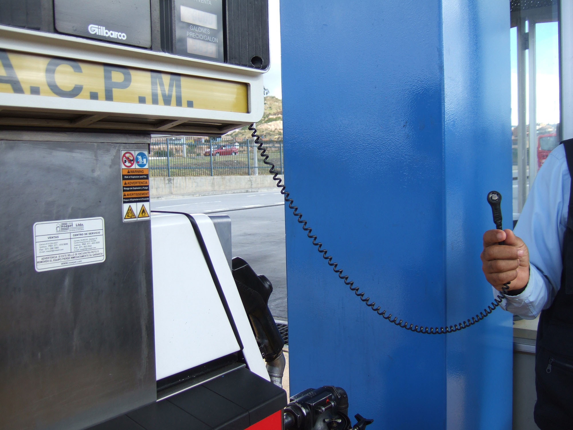
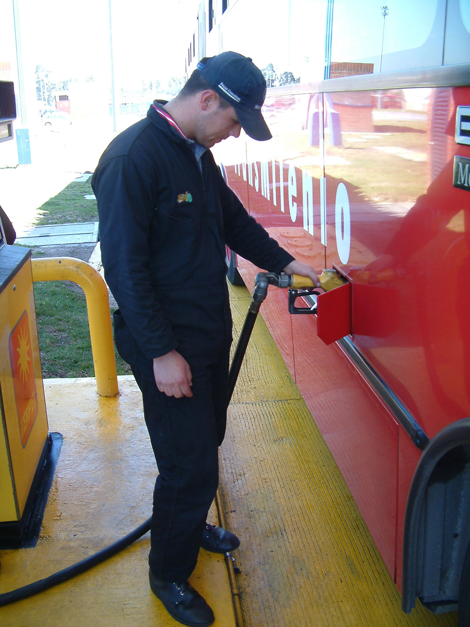
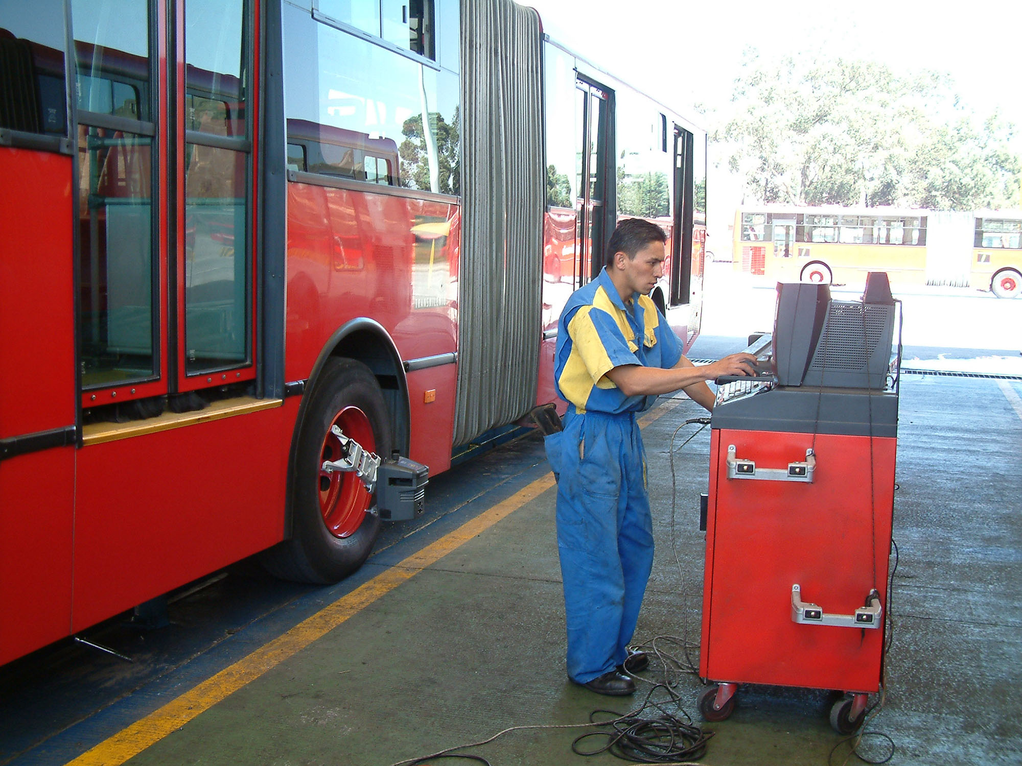
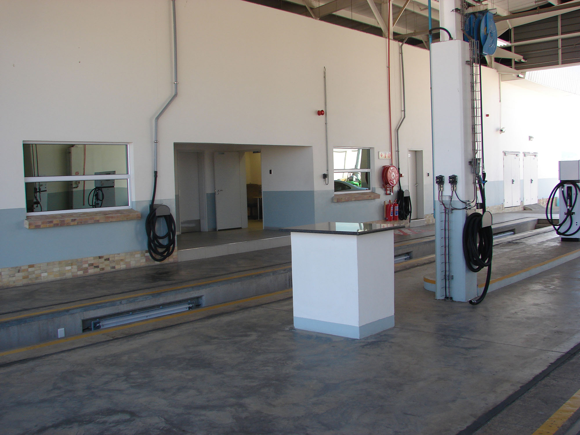
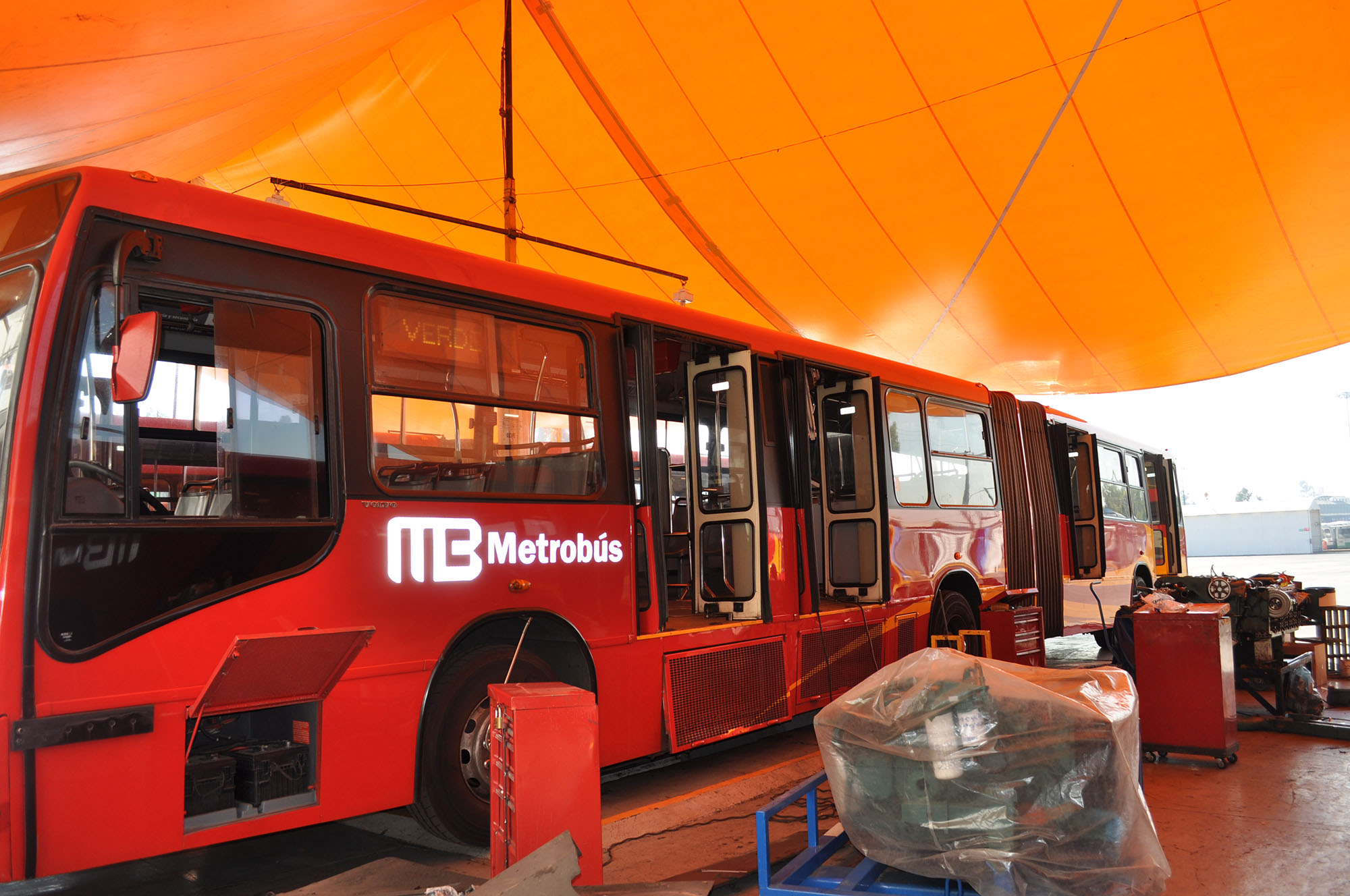
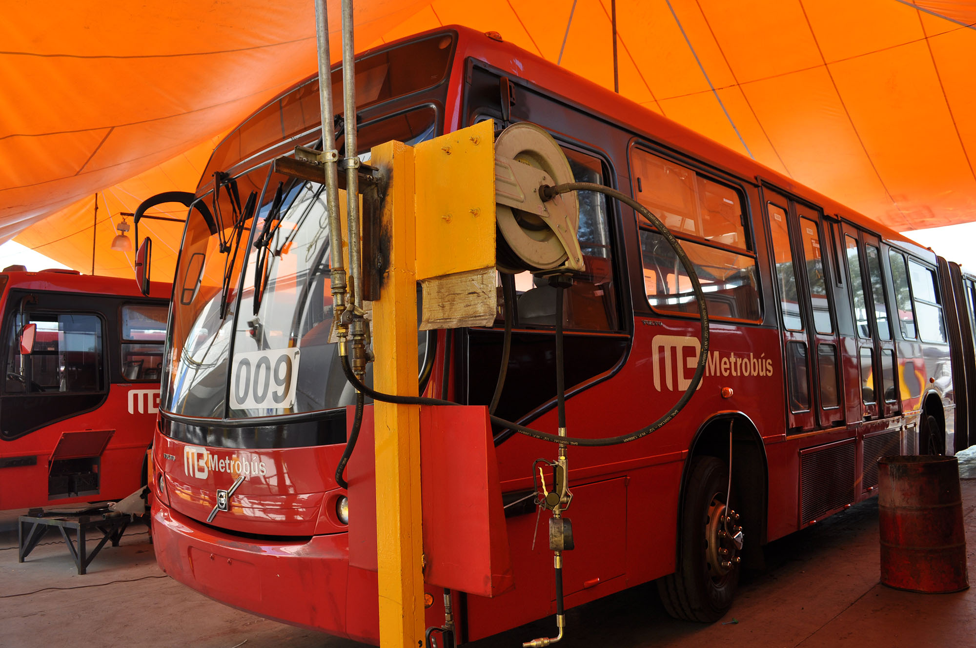
If the bus is classified as “green,” it will typically first move to refueling. Here fuel levels and vehicle kilometers are checked as a way of monitoring usage and operating costs. In Bogotá, a digital monitoring device records the pertinent vehicle information upon entering the refueling area (Figure 26.4). If required, the vehicle will be refueled at this time.
From the refueling area, the vehicle will likely be either washed or placed in a parking bay. The exterior of the vehicle will typically be washed once per day. Most often, the washing occurs after the vehicle’s final run of the day. The vehicle’s interior may be cleaned upon each entry into the depot area, even if the vehicle is to return for the afternoon-peak period. Maintaining a pristine interior area does much to send a positive message to the customer as well as to psychologically discourage littering. In some systems, such as the Quito Ecovía corridor, the vehicle interior is cleaned after each pass through the corridor. The cleaning, in this case, is actually done at the terminal platform (as opposed to within the depot area).
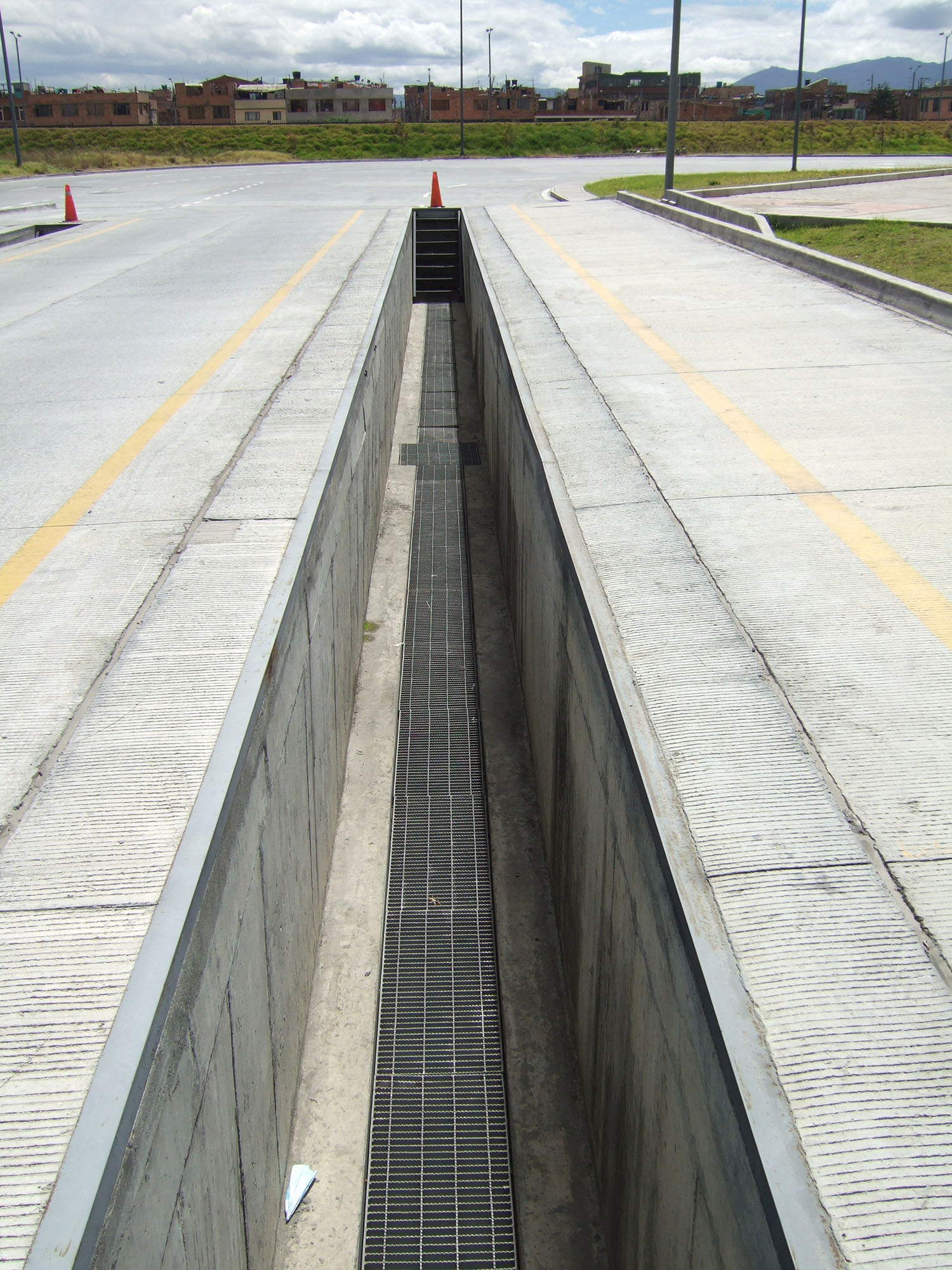
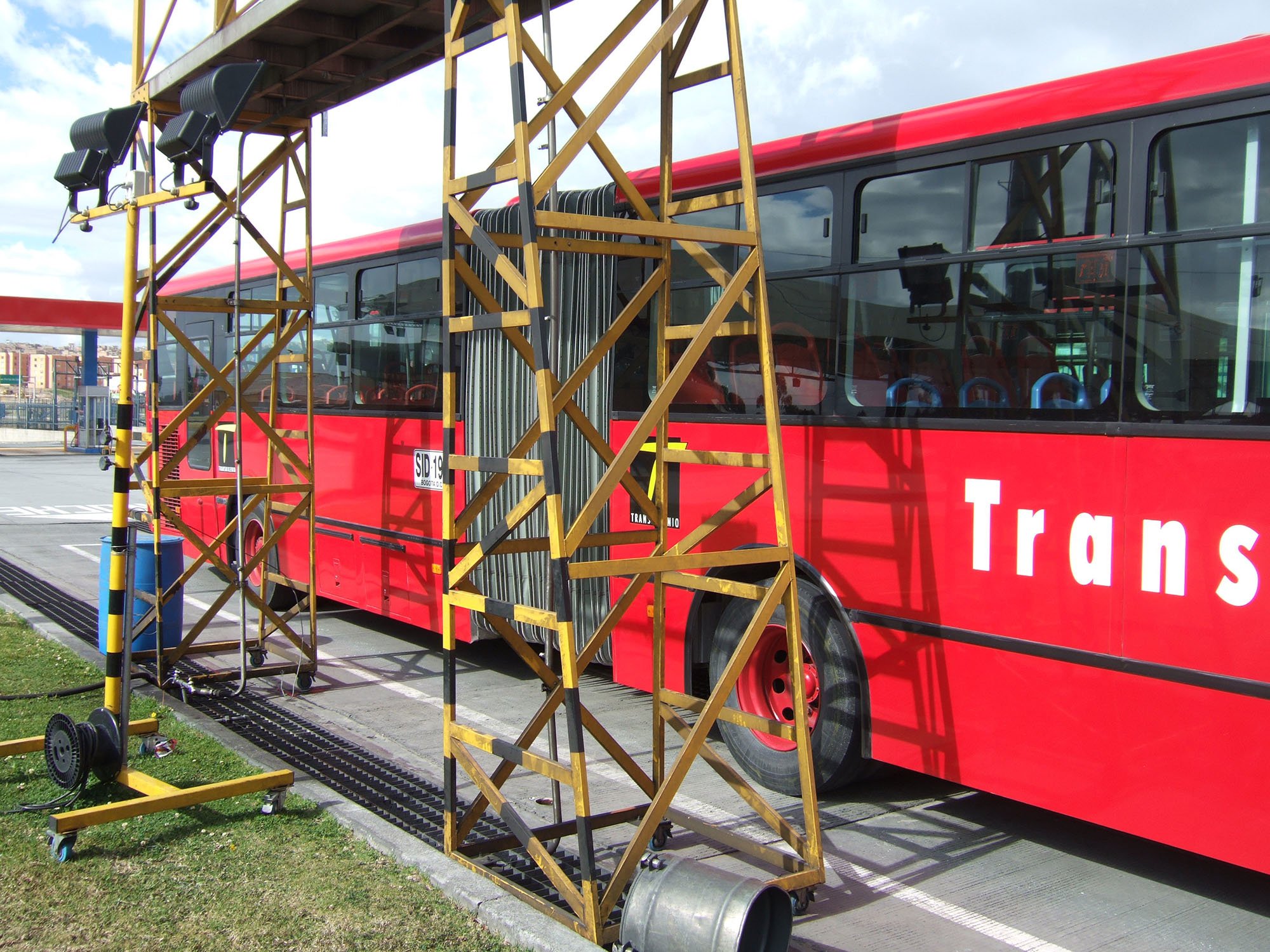
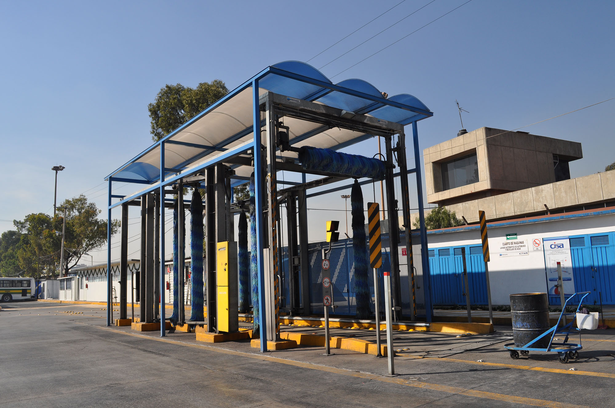
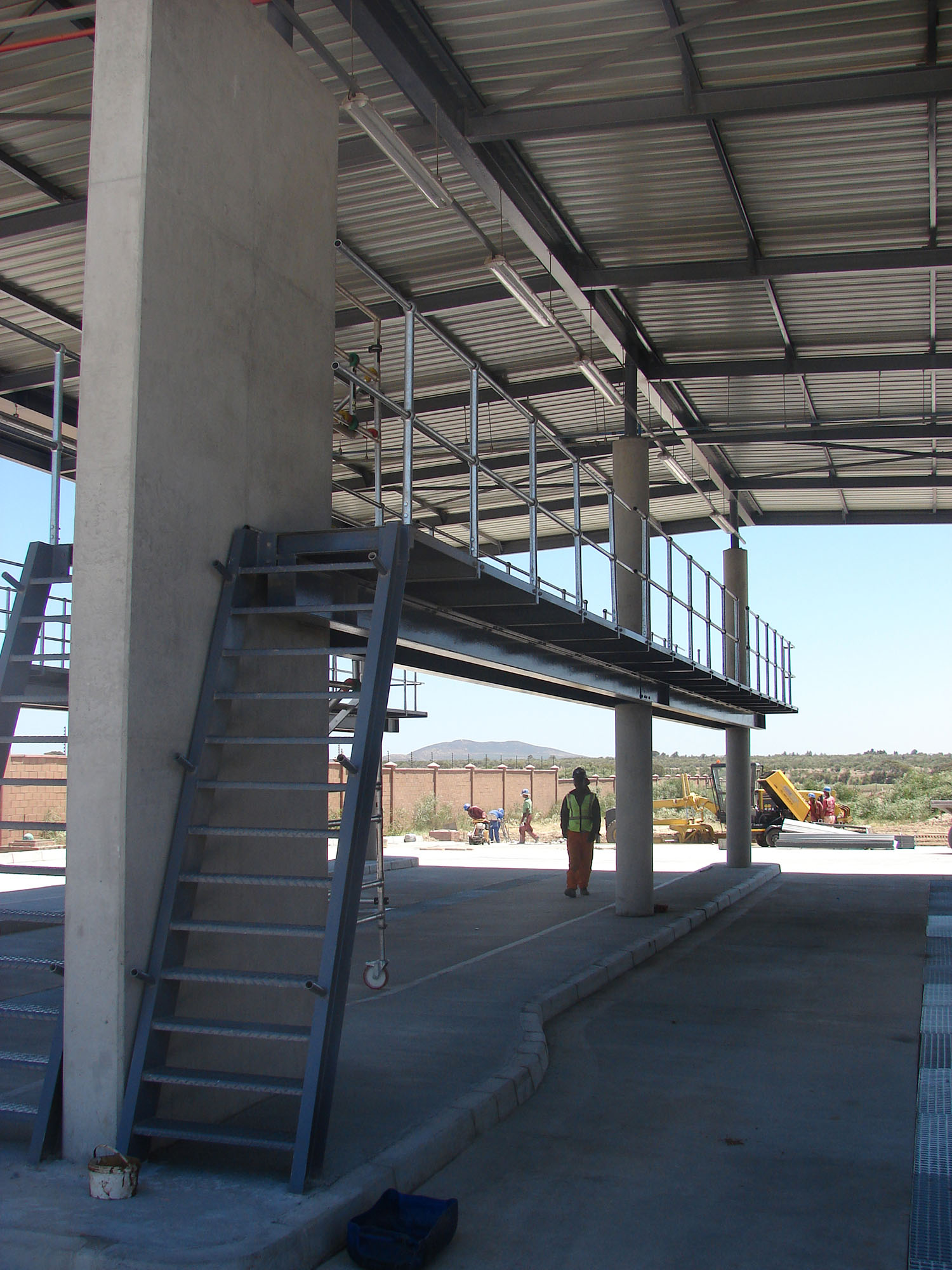
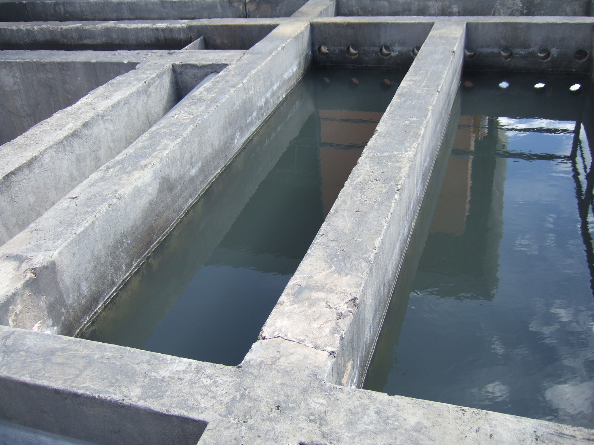
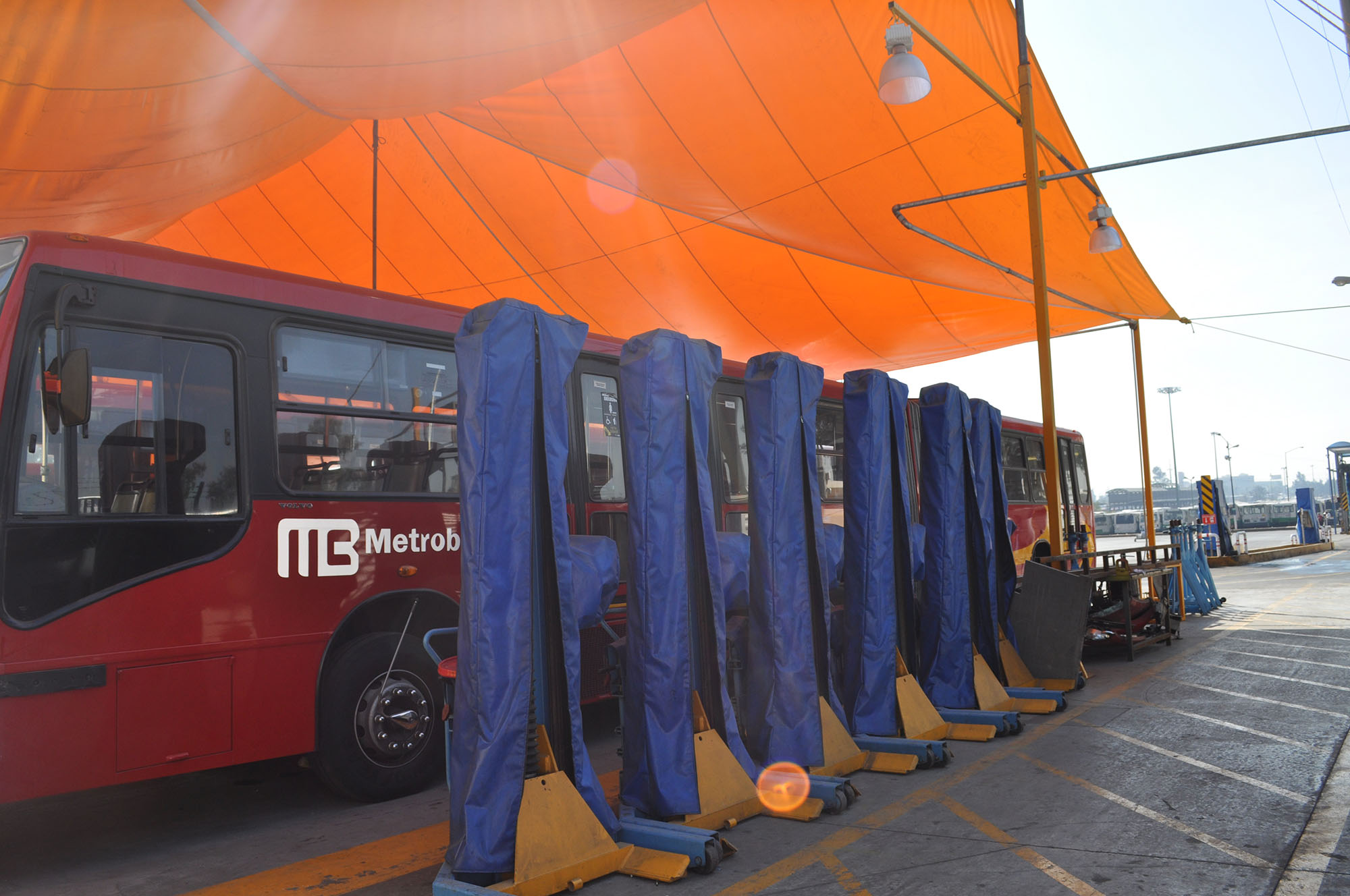
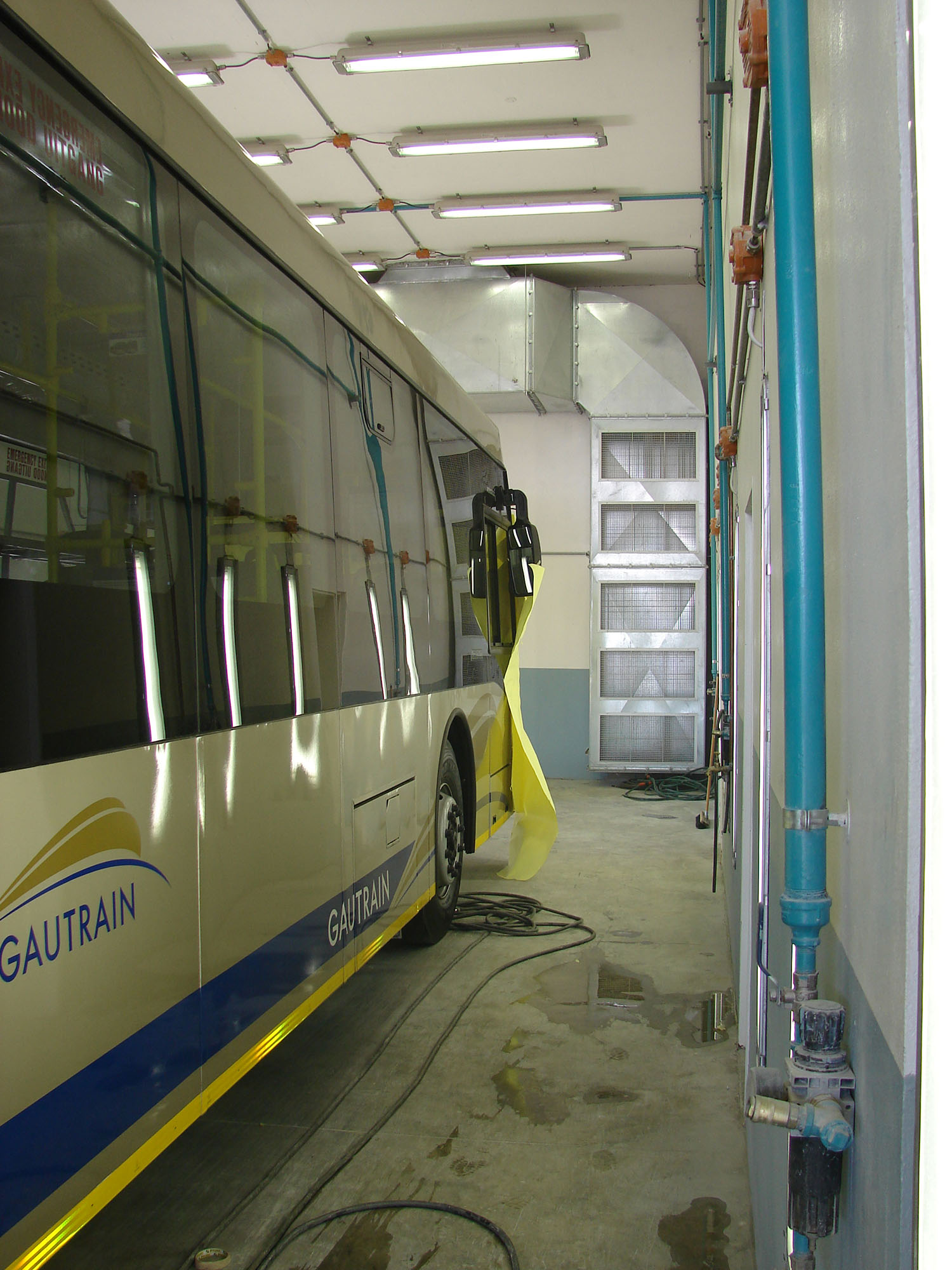
The washing area should be designed to facilitate easy access to all parts of the vehicle. A channelized pit with drainage permits the washing of the vehicle’s underside (Figure 26.6). Special scaffolding equipment permits washing of the vehicle’s roof (Figure 26.7). Alternatively, the washing area can be contained within a building, where stairs and catwalks can be provided to gain access to the vehicle roof for cleaning purposes (Figure 26.9). Vehicle washing machines can also be installed, but this needs to weighed against the cost of these machines, the number required to meet the peak demand for washing, and the speed at which hand washing can be achieved.
In some depots in Bogotá, water-recycling facilities have been established in order to permit reuse of the water from washing (Figure 26.10). Such recycling not only improves the environmental aspects of the system but can also reduce operating costs.
If the BRT vehicle is classified as “yellow,” it is moved to the minor maintenance area (Figure 26.11). From the minor maintenance area a vehicle may return to service the same day or by the next morning. This area may also perform routine checks on the vehicle based on the total kilometers travelled.
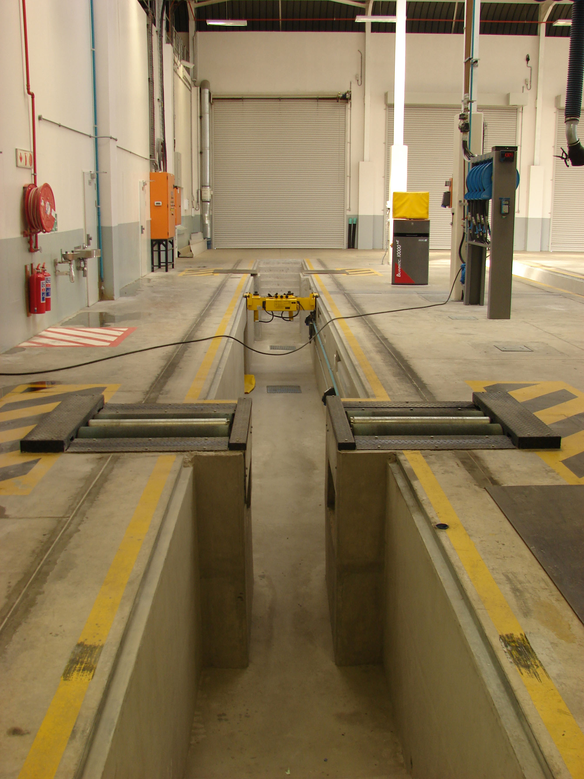
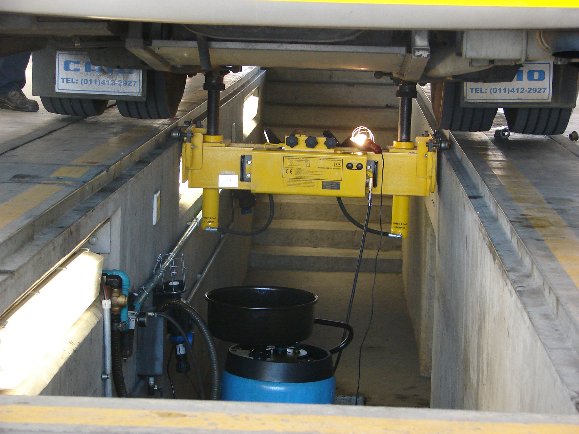
If the vehicle is classified as “red,” it goes to the major maintenance building, and is replaced by a standby vehicle. The major maintenance building includes a range of facilities, namely vehicle service bays, maintenance offices and facilities, and parts storage. A channeled work space (or pit) below each vehicle permits repair staff to easily access the vehicle chassis for inspection and repair (Figures 26.12 and 26.13). Typically, a certain percentage of vehicles (5 to 10 percent) of the fleet are held in reserve to replace vehicles undergoing maintenance. However, in other systems, a just-in-time (JIT) philosophy prevails where all vehicles are fully utilized.
Typically, seven vehicle-service bays are required per hundred vehicles based at the depot. Of these seven bays, four bays should be equipped with service pits, two bays without service pits, and one bay should be separate and used as a spray painting bay (Figure 26.18).
- The one service bay with a pit should be equipped with brake testing equipment (Figure 26.19);
- The pit lengths should exceed the length of the longest vehicle by at least a meter on either end of the pit, to ensure access to the pit once the vehicle has been parked over it. The pits should be equipped with hydraulic lifting equipment to facilitate lifting of the chassis to do wheel repairs (Figure 26.20);
- One or both of the service bays without pits, should be equipped with stairways and catwalks, so that the air-conditioning units of the vehicles can be inspected and repaired;
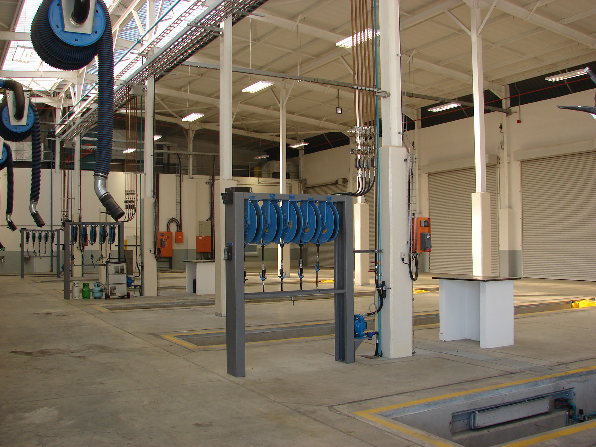
- All lubricants, oils, etc., required for the maintenance of the vehicles can be piped through the building to each of the service pits (Figure 26.17).
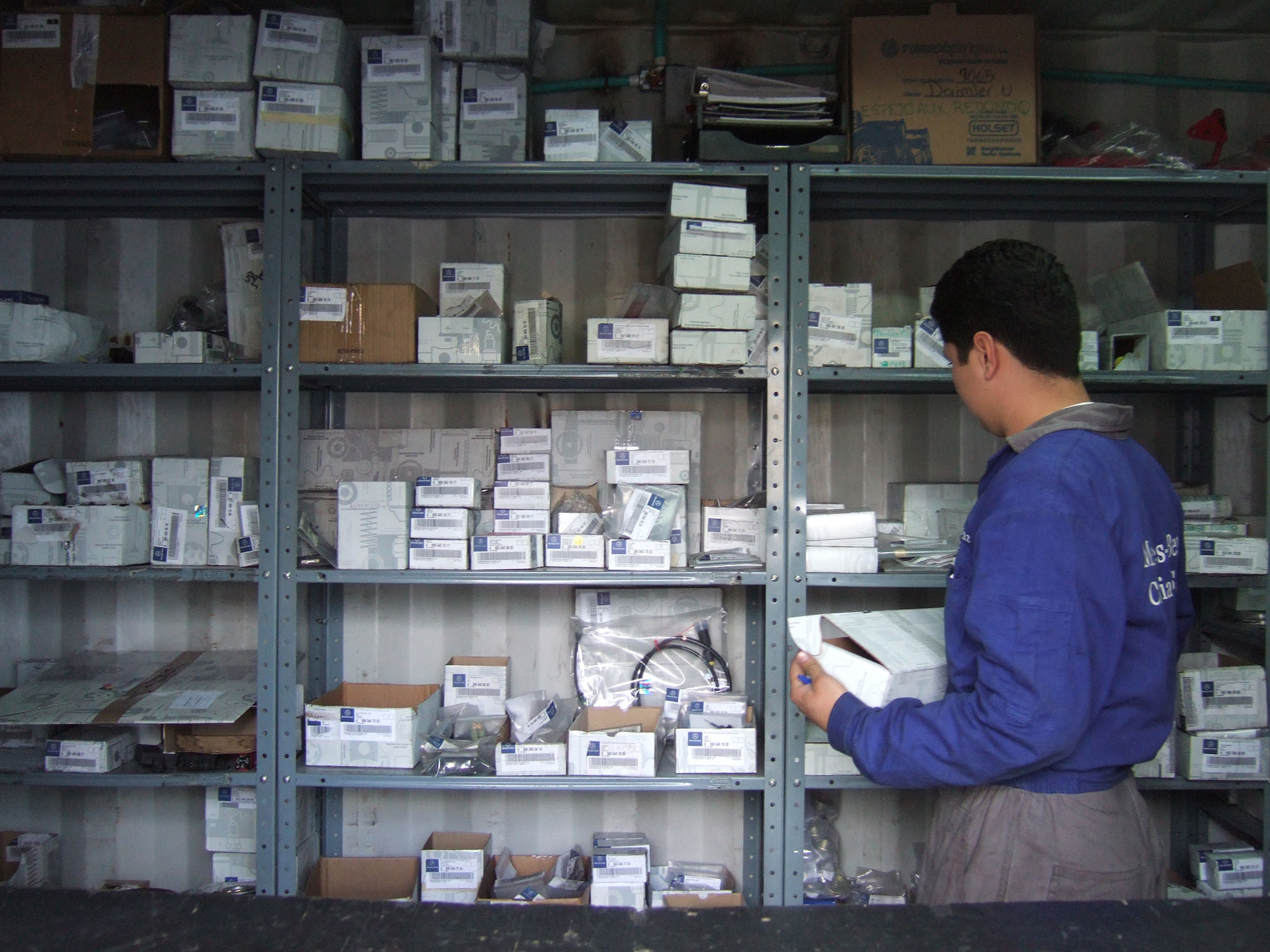
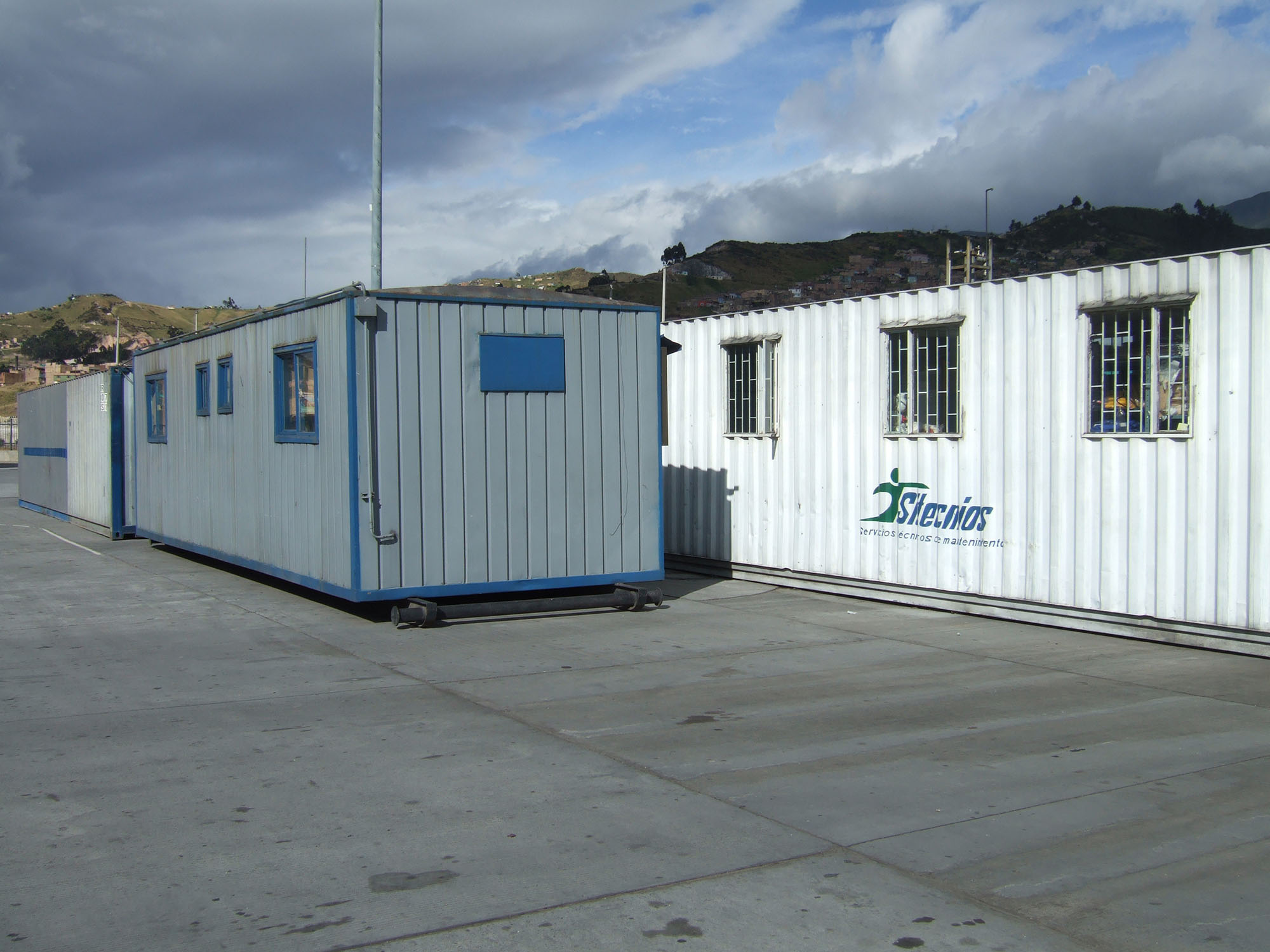
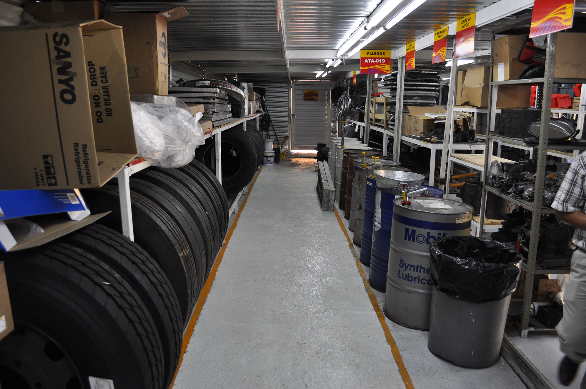
Spare-parts storage is typically located near the maintenance and repair areas. The extent to which parts storage is required depends in part on the procurement practices of the particular operating company. Some firms may prefer to purchase in bulk, and thus retain a fairly substantial spare-parts inventory. In other cases, a just-in-time (JIT) philosophy may prevail, and the operating company may hold just a minimum number of spare parts (Figure 26.21). The operating company Sí 99 in Bogotá maintains a very lean inventory in order to minimize costs. In fact, the spare parts are part of the contractual arrangements with the BRT vehicle supplier who must provide on-site service. Since this type of close manufacturer-operator relationship was not foreseen at the outset of the depot construction, facilities were not provided for the manufacturer offices. Instead, provisional trailers have been set up to accommodate manufacturer offices and supplies (Figure 26.22).
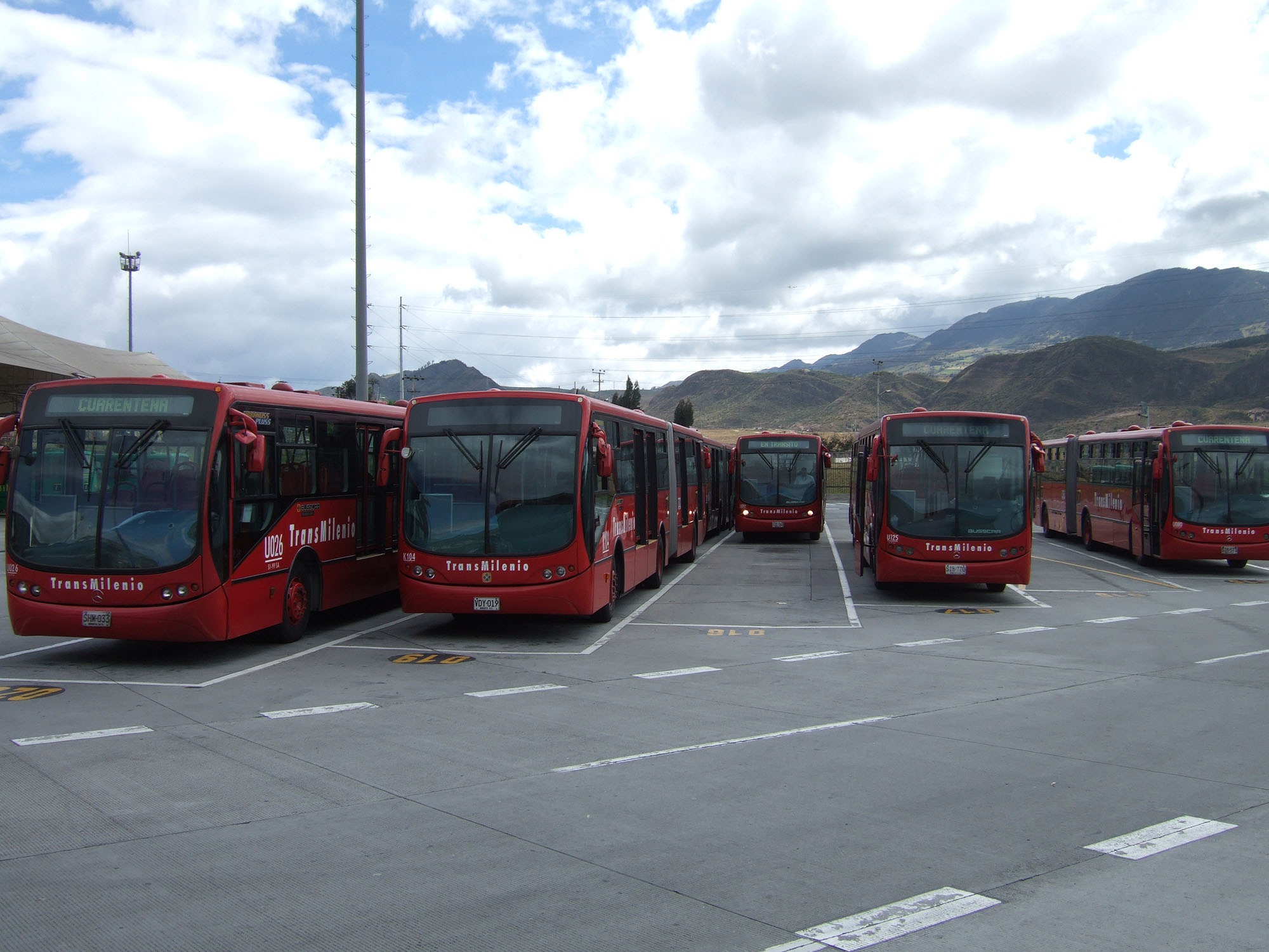
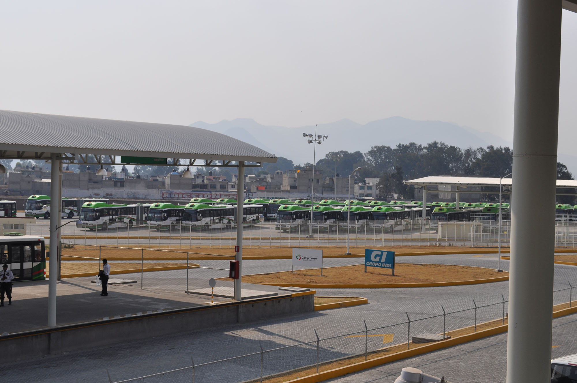
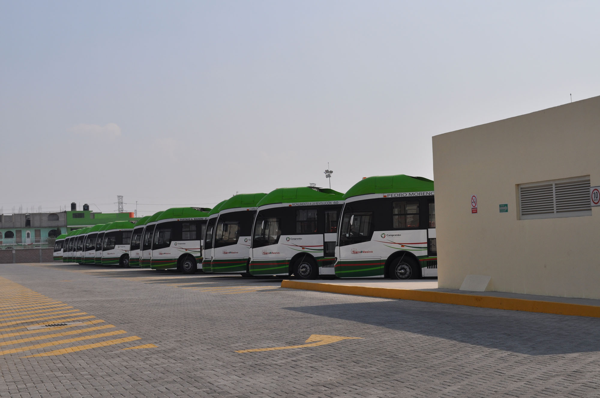
Sufficient parking space must be provided to hold the vehicle fleet during off-hour periods. The parking-area design should also maximize easy entry and departure movements of vehicles. The numbering and assignment of the parking bays can provide efficient control over the fleet (Figure 26.24).
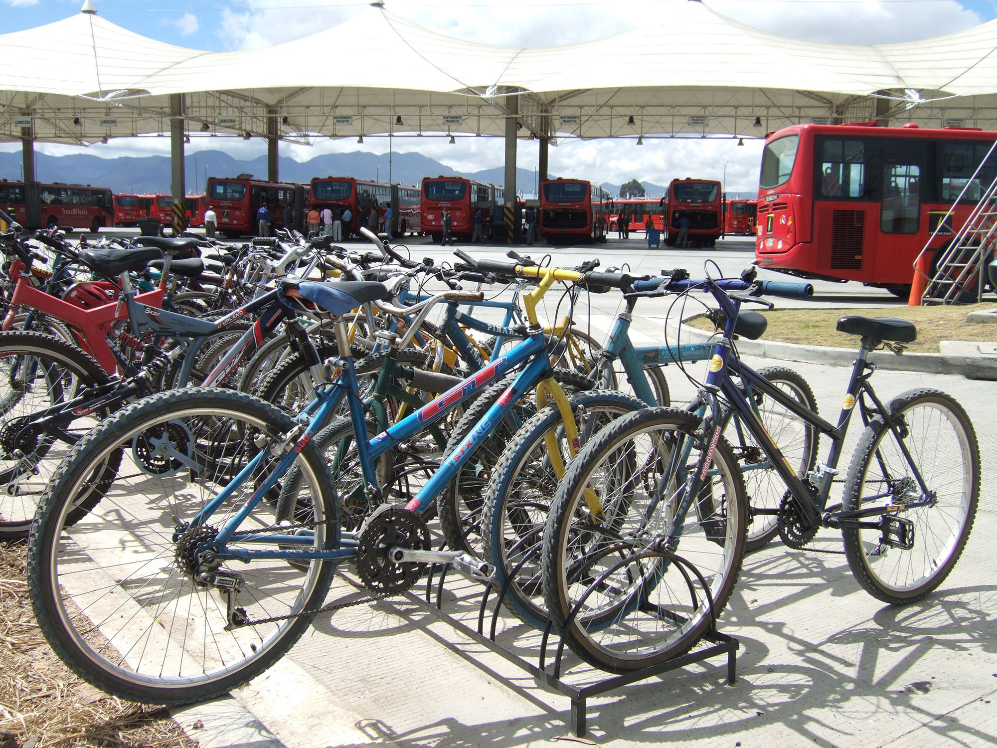
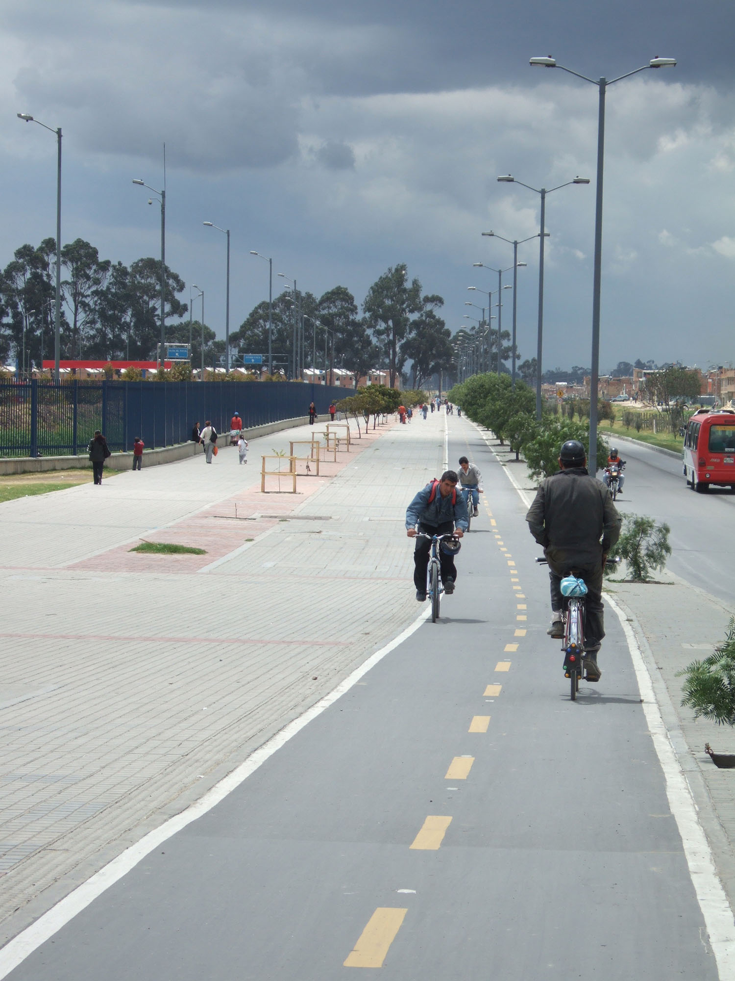
Some private-vehicle parking may also be required at the depot area. Certainly, access for emergency vehicles should be included in the design. In some cases, not all employees may be able to utilize the BRT system to arrive at work. Since the drivers, mechanics, and other employees will likely need to arrive prior to the start-up of the system in the morning, alternative arrangements should be considered. At the Bogotá Américas depot, bicycle parking is provided for the staff (Figure 26.27). Providing good pedestrian and bicycle access to the depot area helps encourage staff to utilize sustainable forms of transport to get to work (Figure 26.28).
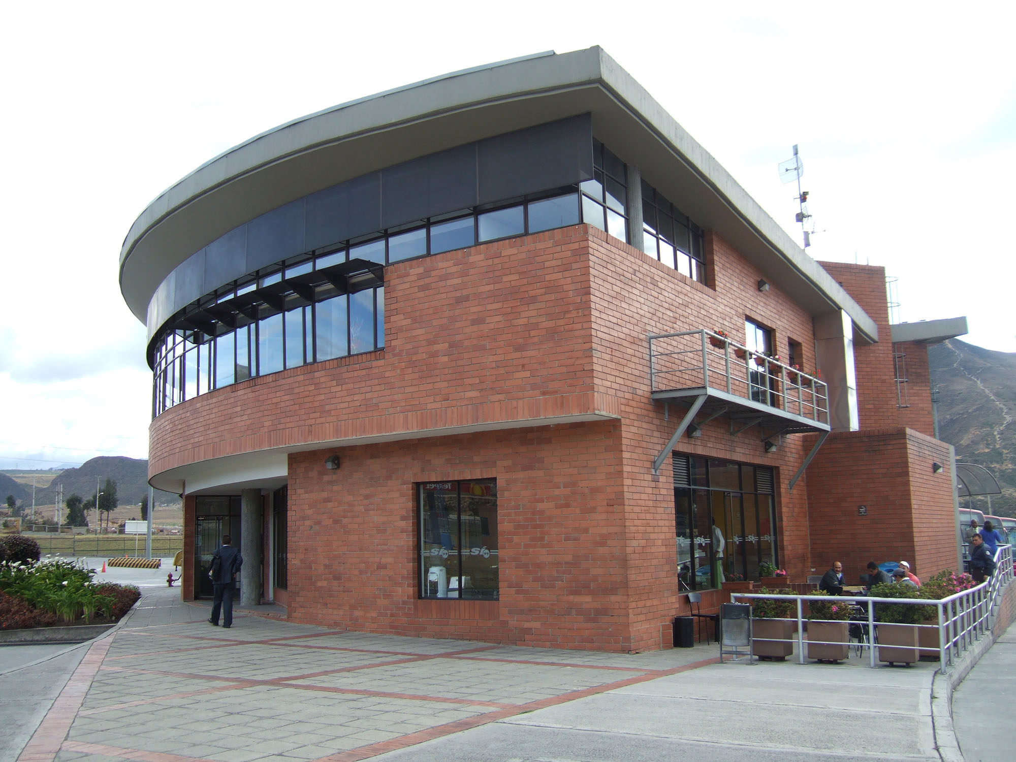
It is best to locate the offices for operating companies at or near the depot. By being located at the depots, operating company officials can better monitor activities and oversee staff (Figure 26.29). The administrative offices may also include conference and training facilities.
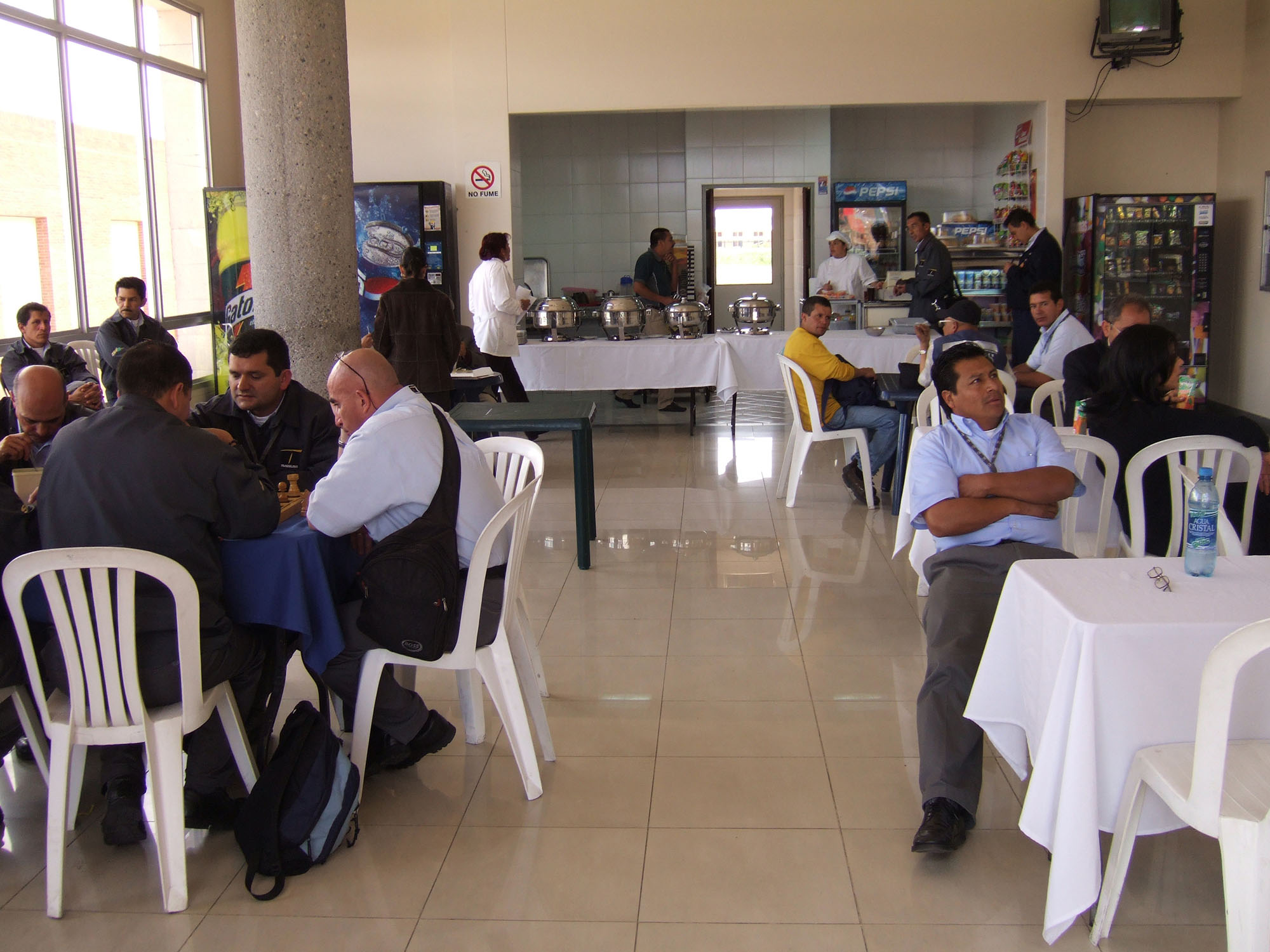
Finally, the depot area should also provide facilities catering to the needs of staff, such as drivers, mechanics, and administrative workers. These facilities may include showers and lockers, luncheon areas, and recreational areas (Figure 26.30). The workplace environment should be designed to allow drivers and other employees an opportunity to relax after or in-between shifts, as well as prepare prior to the start of a shift.