21.2Infrastructure Design Process
The designer has an obligation to provide an appropriate conceptual model for the way that the device works. It doesn’t have to be completely accurate but it has to be sufficiently accurate that it will help in both the learning of the operation and also dealing with novel situations.Don Norman, scientist and psychologist, 1935–
The design of the infrastructure takes place in three basic stages, though in practice it is often more of an evolutionary process. In the first stage, conceptual designs will be developed based on the emerging service plan. The second and third stages—the preliminary and detailed engineering design follow once the conceptual study and the initial cost estimates warrant a commitment toward a particular design. Thus, for each infrastructure component discussed in this section (e.g., bus lanes, stations, terminals, etc.), the planning team will first complete a conceptual study prior to moving towards more detailed engineering plans and specifications. Most of the conceptual design issues are addressed in the operations chapters. This chapter provides additional detail to the physical design process necessary to complete the conceptual design. Preliminary and detailed engineering will follow general engineering practice.
21.2.1Conceptual Design
The infrastructure conceptual design should provide a sufficient level of detail so that decision makers may properly evaluate the cost, functionality, and aesthetics of the proposed system.
Even for a basic conceptual design, a considerable knowledge of the corridors will be required. A full audit and inspection of each corridor segment will allow the design team to understand the nuances of the corridor as well as identify the most problematic areas. It is also critical to know which services will operate on the corridor, as well as projected target yearly ridership on each route (Chapter 6: Service Planning). This will be a major factor in determining infrastructure sizing and accommodation of routes that may enter and exit the corridor at various locations.
Particular attention should be given to intersections and proposed station locations.
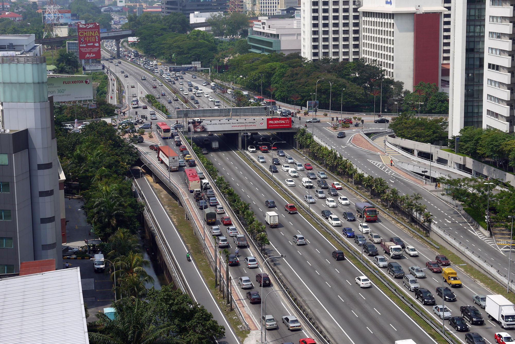
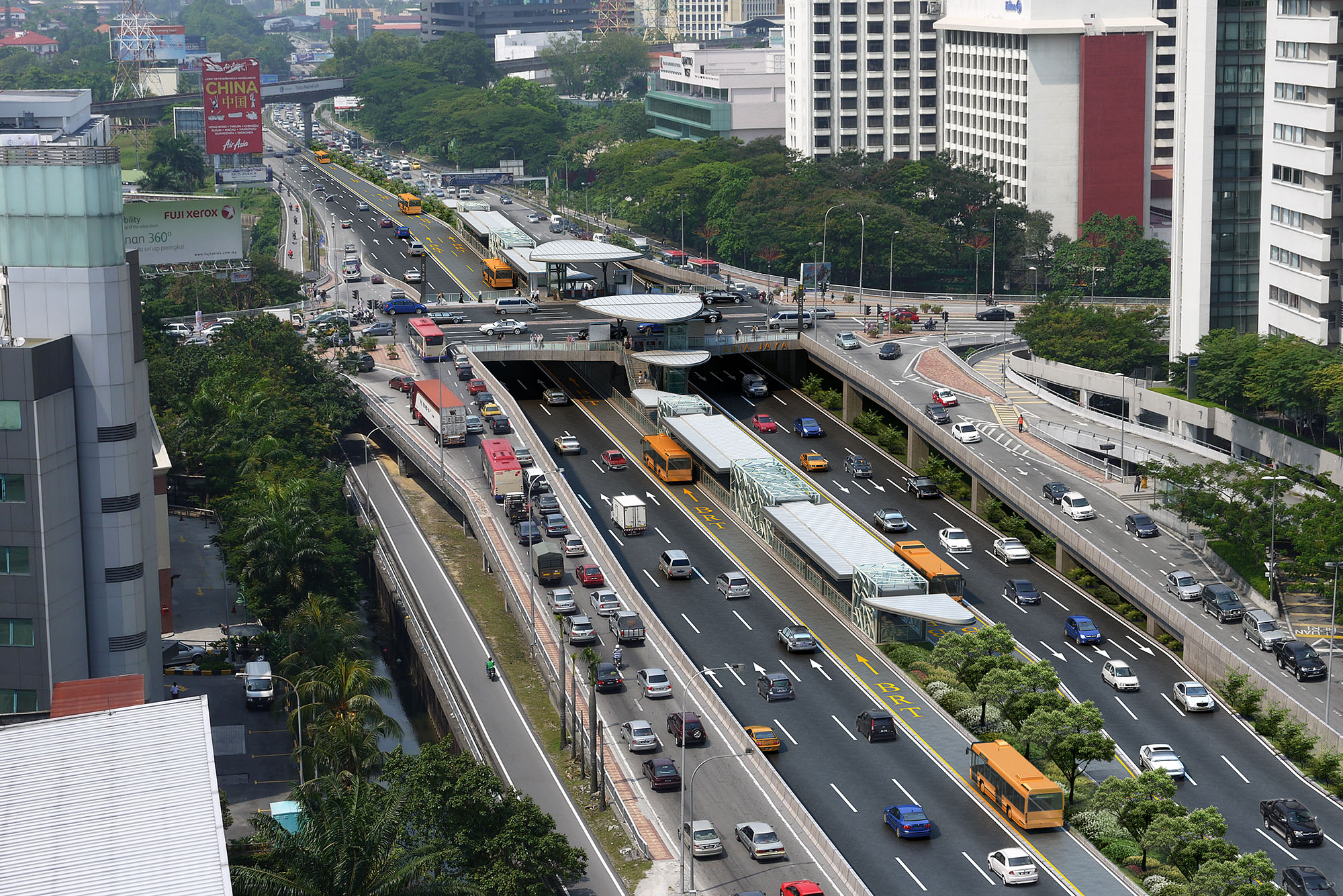
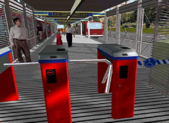
Once the conceptual stage is completed, it will be possible to develop fairly accurate artistic renderings of the system infrastructure. These initial renderings will help decision makers and interested parties begin to visualize the system. Figures 21.2 and 21.3 show an artistic impression for the Guangzhou, China, BRT system.
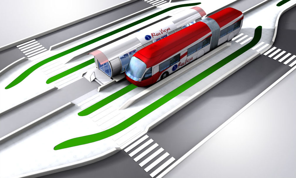
Renderings can also be an important part of simulation videos that give decision-makers a fairly realistic idea of the proposed system. Renderings for the proposed Johannesburg, South Africa, Rea Vaya system helped secure necessary political support (Figure 21.4).
Likewise, early renderings in Bogotá helped communicate the project to a range of stakeholders, including the general public. It is critical, however, that these renderings be presented as accurately as possible.
The contracting of the design consultants can take on several different forms. In some cases, the design is carried out by one firm while the ultimate construction is to be done by another firm. This option avoids any problems with conflicts of interest between the design and construction work. For example, if the design and construction firm are one and the same, then there could be a tendency to choose designs that minimize construction costs. However, such a design may not be optimal from an operational perspective. If multiple firms are contracted, for example, for design, service planning, and construction, all should be in frequent communication to ensure the alignment of system objectives. Ideally one lead firm should carry out the detailed design as well as guide the actual implementation by all system subcontractors.
Combining the design and construction work into a single contract, though, does hold some advantages. With a single firm undertaking both these tasks, there is a greater degree of continuity between the design and construction. The single contract can also ensure a greater degree of responsibility in delivering the project.
21.2.2Preliminary and Detailed Design
Once a conceptual design is completed and initial cost estimations are within an acceptable range, then a preliminary (followed by a more detailed) design process can begin. The detailed engineering design and specifications will be the basis for the actual construction work. The detailed design will also permit construction firms to make more accurate cost estimates within the construction bid process.
It is during the preliminary design phase where public comment is often sought and is useful to the project. At the preliminary design phase, the conceptual design is being tested for robustness and input from the local community and local municipal officials must be sought to refine the layout and design, discussed in detail in Chapter 10: Public Participation. Once the preliminary design phase is complete, changes to the layout and design concept are counterproductive, as this leads to expensive redesign and abortive effort.
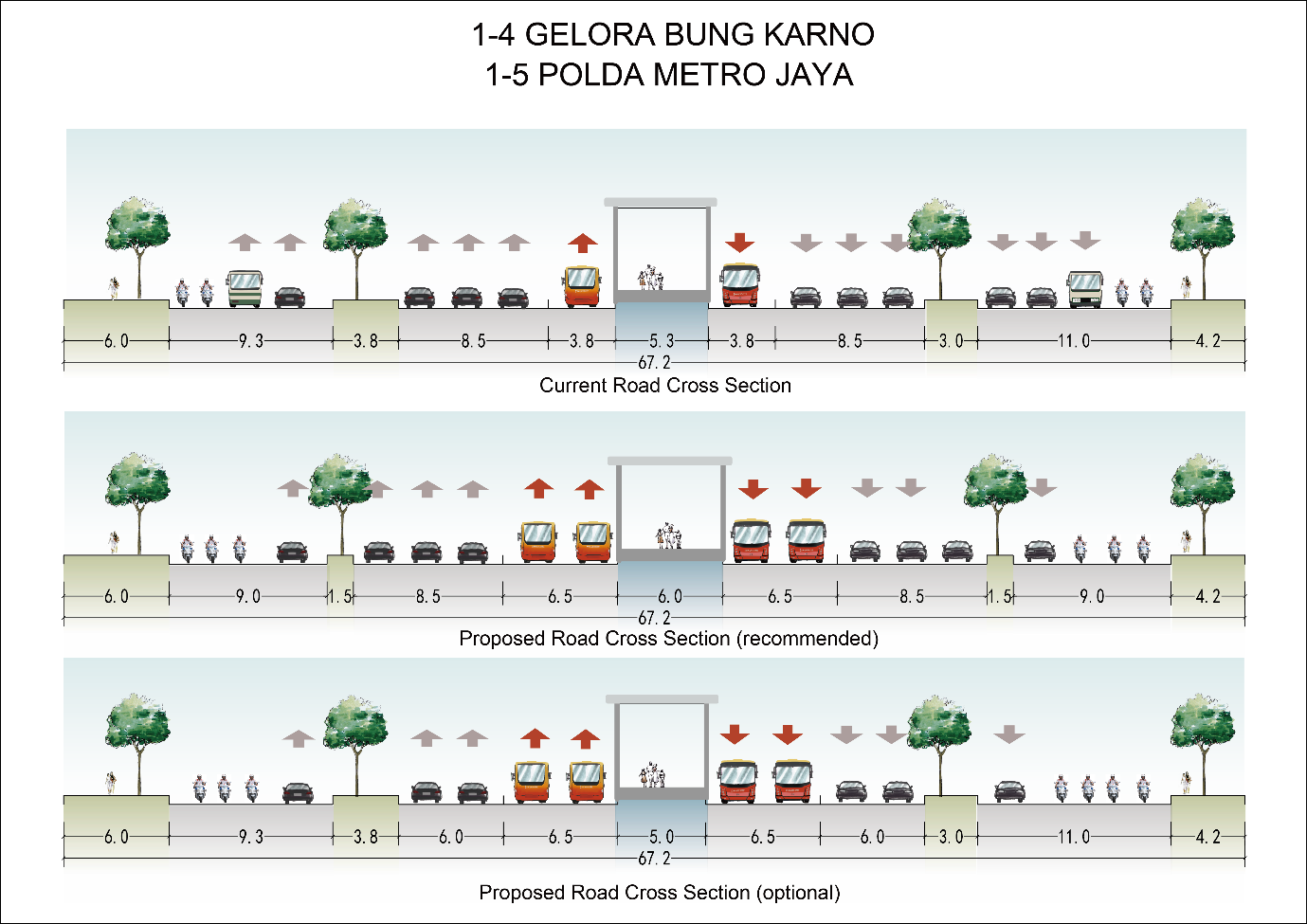
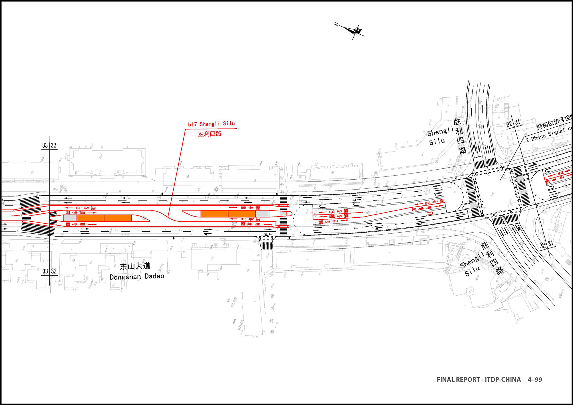
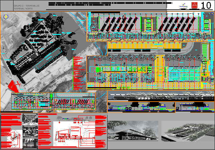
Given the topographical changes throughout any corridor, each section of roadway will have its own unique design. Detailed drawings generated from software such as AutoCAD will be required along each segment. Other drawings will begin to provide some of the more precise dimensional and structural details that will later be transformed into highly detailed engineering drawings. Figures 21.8 and 21.9 are examples of these types of drawings.
The bulk of detailed design terminates with the completion of the final construction drawings, project specifications, tender documentation (including conditions of contract), and full bill of quantities (with a complete capital cost estimate). The design firm, if different from the construction firm, should play a leading role during construction to ensure that contractors follow the designs, and to react to myriad contingencies and circumstances arising during construction.