24.6Allowing BRT Turns
An Englishman, even if he is alone, forms an orderly queue of one.George Mikes, writer, 1912-1987
While service plan simplification and organization may, to an extent, minimize turning movements for BRT vehicles in the busway, by concentrating service access to the corridor in a few intersections, turning is necessary and desired where it best serves the demand (in opposition to allowing it where it is convenient by geometry). By planning BRT routes that change between corridors (i.e., with turns), easy platform transfers for the customers are made possible, better, or not even necessary for most users. Thus, turning movements by BRT vehicles should be an integral part of designing an effective overall route structure. As the BRT system expands and provides an increasingly dense network of lines, the connections between these lines become more complex. While a BRT system expands, a growing number of trunk corridors crossing each other is expected.
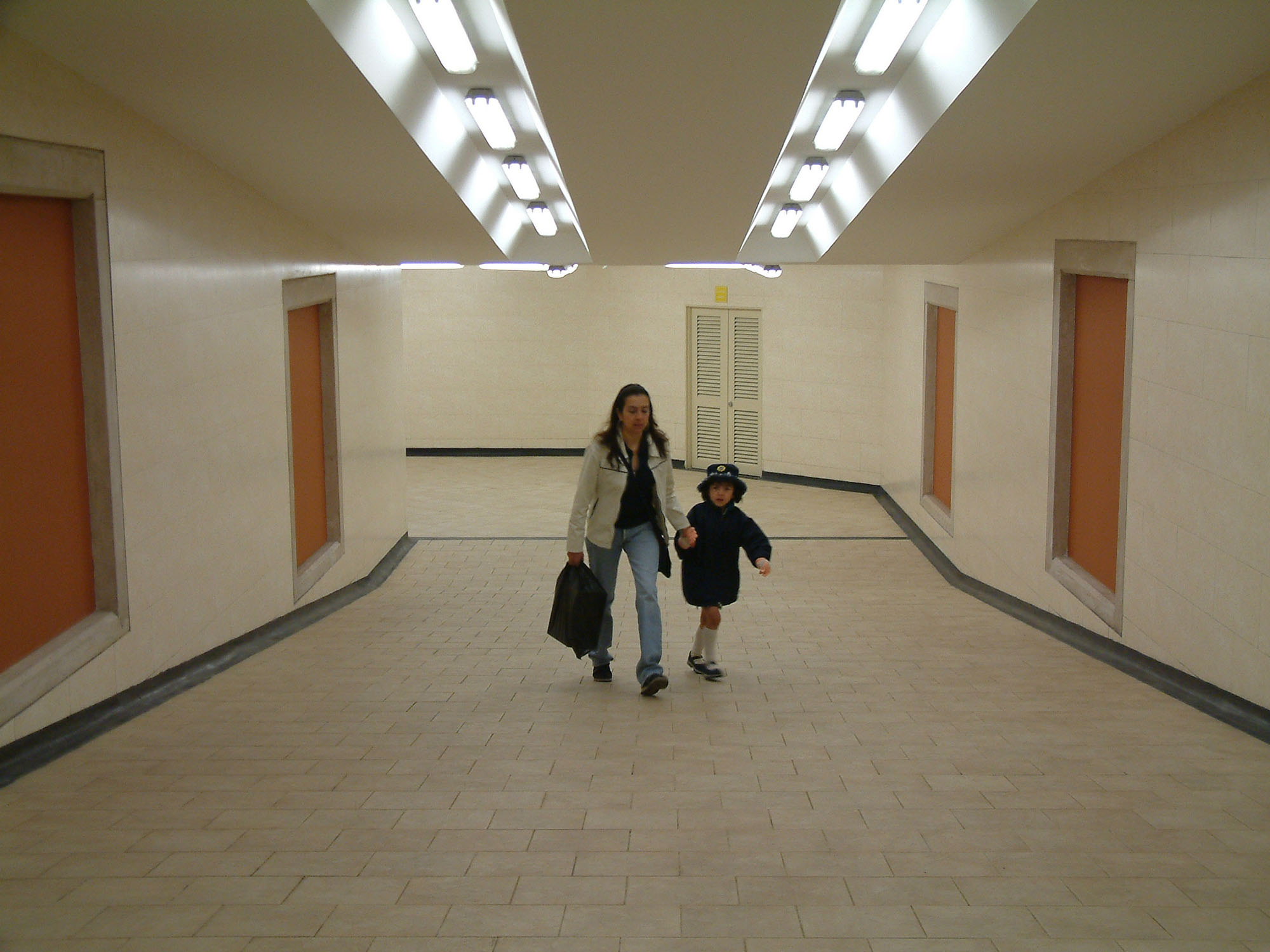
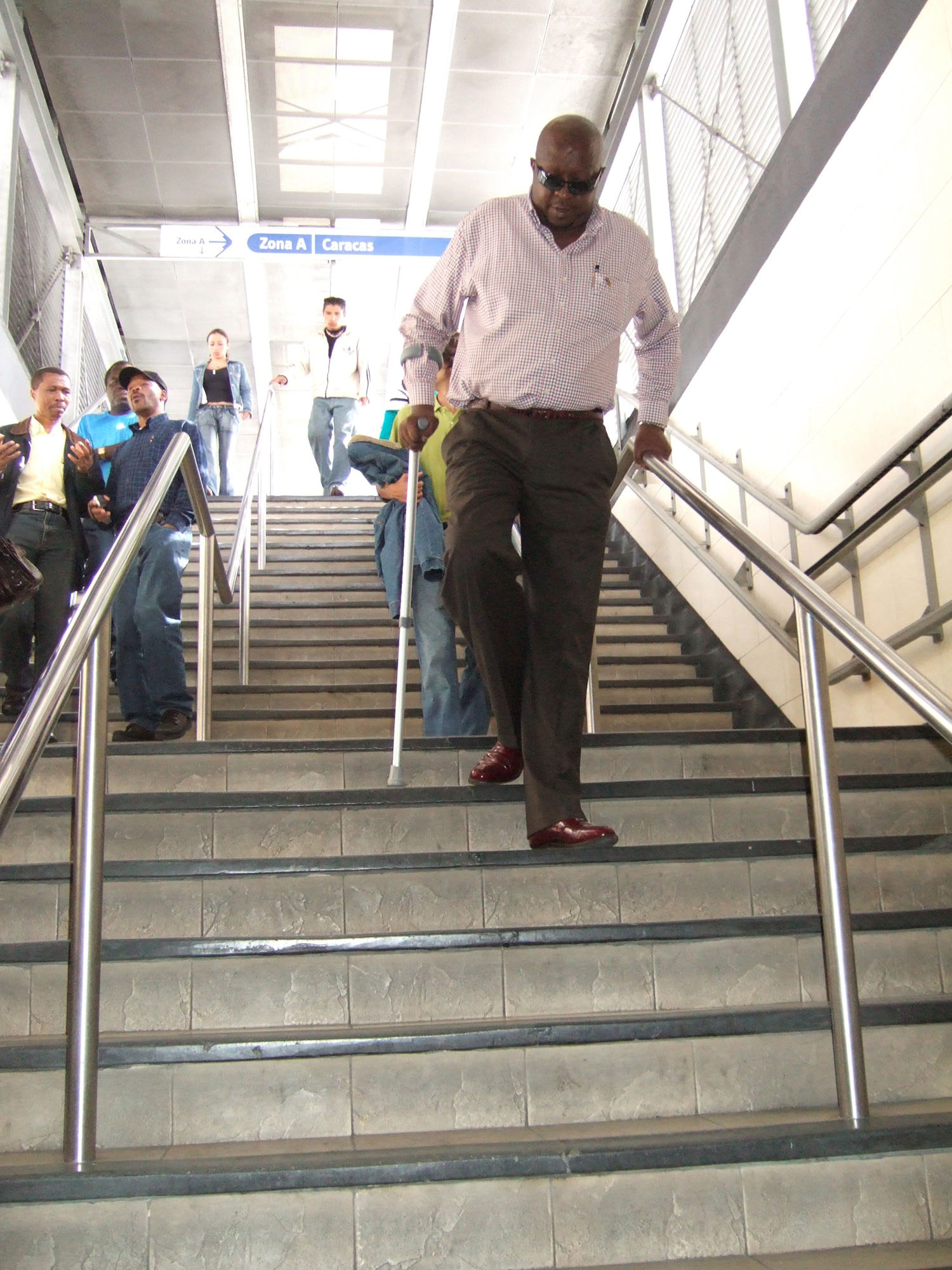
The costs of not allowing turning movements by BRT vehicles are quite evident, especially in terms of customer convenience. Quito’s three BRT corridors (Trolé, Ecovía, and Metrobus-Q) all operate as independent corridors, despite each intersecting one another at several points in the city. At one of the critical intersections between two intersecting BRT corridors in Bogotá (Caracas and Jimenez), customers must transfer by negotiating passages along stairs and an underground tunnel (Figures 24.51 and 24.52). In both these examples, allowing turning movements by the BRT vehicles could have permitted simpler and more convenient platform transfers for the customer. Furthermore, constructing connecting pedestrian tunnels can add much to the overall infrastructure costs of the system. This is copying the bad parts of rail systems. In the Bogotá situation, customer convenience has been significantly increased by allowing turn movements and direct transfers between the Caracas and Jimenez corridors.
There are several solutions to allow BRT vehicle turning that avoid consuming much of an intersection’s capacity—mostly needed for cars in the intersection—and the appropriate solutions will depend on the available budget and right-of-way, the number of vehicles in the BRT system and their turning volumes, and the level of mixed traffic and its turning volumes. The optimal solution will be location-specific and each intersection must be evaluated and optimized separately. Here are common options for busway turning movements:
- Dedicated turning lanes and additional signal phases for BRT vehicles;
- BRT vehicles operating in mixed-traffic turning lanes;
- BRT turning movements prior to the intersection;
- Transform the crossing into a roundabout;
- Grade separation (discussed in Section 24.10).
24.6.1Dedicated Turning Lanes and Additional Signal Phases for BRT Vehicles
A dedicated turning lane for BRT vehicles has the advantage of keeping the BRT vehicles in a controlled space at all times (see Figure 24.53). This arrangement may require an additional signal phase if there was no previous cross-traffic-turn phase. Otherwise, the dedicated turn would take place at the same time that the mixed traffic is allowed to turn left.
Possibly the greatest challenge to this configuration is finding the physical space to place the additional turning lane. The roadway would likely have to accommodate at least five lanes (Figure 24.54). If two lanes of mixed traffic in each direction are to be maintained for straight-car movements, then seven lanes of road space would be required.
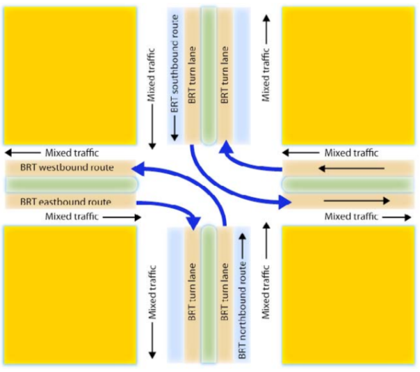
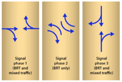
The configuration suggested in Figure 24.54 would require a three-phase traffic signal, as indicated in Figure 24.55, and in the case of a median-station configuration it can provide full access to all route permutations without walking: a southbound vehicle turning east will give customers access to westbound routes via the platform transfer at the first station. In designing this option, one would choose the highest demand routes to receive the transfer-free routing.
In this scenario, one could technically also allow cross-traffic-turn movements for mixed-traffic vehicles for traffic from north and south, but even more additional lanes would be required. Ideally though, mixed traffic should be diverted as proposed in the previous section (Section 24.5: Restricting General Traffic Turning Movements) as the BRT cross-traffic turn phase will usually be very short (like the queue-jumping phase proposed in 24.5.2.1).
If the turning BRT vehicle frequencies are low enough, the BRT-only short phase can accommodate both right and left turns from one direction as BRT vehicles’ drivers can negotiate entrance to the other corridor. That would avoid the need for two waiting lanes for turns.
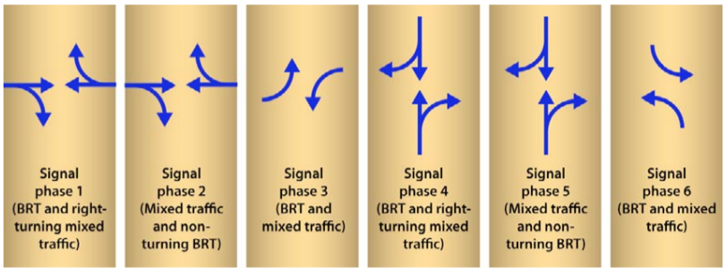
The complexity of dedicated turning lanes obviously increases as turning options for both BRT vehicles and mixed-traffic vehicles increase. In the extreme case of permitting all BRT turning options and all mixed-traffic turning options, then a total of six traffic-signal phases would be required (Figure 24.56). This number of phases clearly holds disadvantages in terms of waiting times for both BRT and mixed-traffic movements and reduces the capacity of the intersection so drastically—besides requiring four lanes, four BRT lanes, and likely six for mixed traffic—that is very likely to not be feasible in a location where two important corridors cross each other.
24.6.2BRT Vehicles Operating in Mixed-Traffic Turning Lanes
In this scenario, all turning BRT vehicles must leave the dedicated busway and enter mixed-traffic lanes. Thus, a cross-traffic-turning BRT vehicle will leave the busway and directly enter the cross-traffic-turn lane for cars. A curbside-turning BRT vehicle must leave the median-side busway and merge to the curbside of the street to reenter the median-side busway on the new corridor.
This technique is the most common solution that has been used in many of the “open” BRT systems, such as in Kunming, China, and is being planned on several “direct services” BRT systems (Figure 24.57). If there is no physical separation of the busway, the merge with the mixed traffic can happen anywhere in the proceeding block. If there is physical separation, it must occur at the previous intersection, or a slip lane must be provided.
From a signal phase standpoint, this option is the easiest to implement, as it does not require changing the signal phase, and does not require any major new infrastructure. However, this option does present serious disadvantages in terms of congestion delay for the turning BRT vehicles, not to mention the assumed inefficiency of four stages to mixed traffic. Further, if the mixed-traffic congestion is heavy, the BRT vehicles attempting to turn may not be able to readily leave the busway, and thus can cause delays to all BRT vehicles, even those vehicles continuing in a straight routing. The BRT vehicle turning right has particular challenges since it must essentially cross all mixed-traffic lanes both before and after the intersection. Attempting these lane changes is particularly difficult if the system is using 18.5-meter articulated vehicles or 24-meter bi-articulated vehicles.
Any time BRT vehicles must leave an exclusive busway operation and enter mixed-traffic lanes the system loses a certain amount of psychological status with the customer. Mixed-traffic operation makes the system much more akin to a conventional bus system rather than a highly efficient public transport system.
24.6.2.1Queue-Jump Signalization for BRT Vehicles (Pre-Signals)
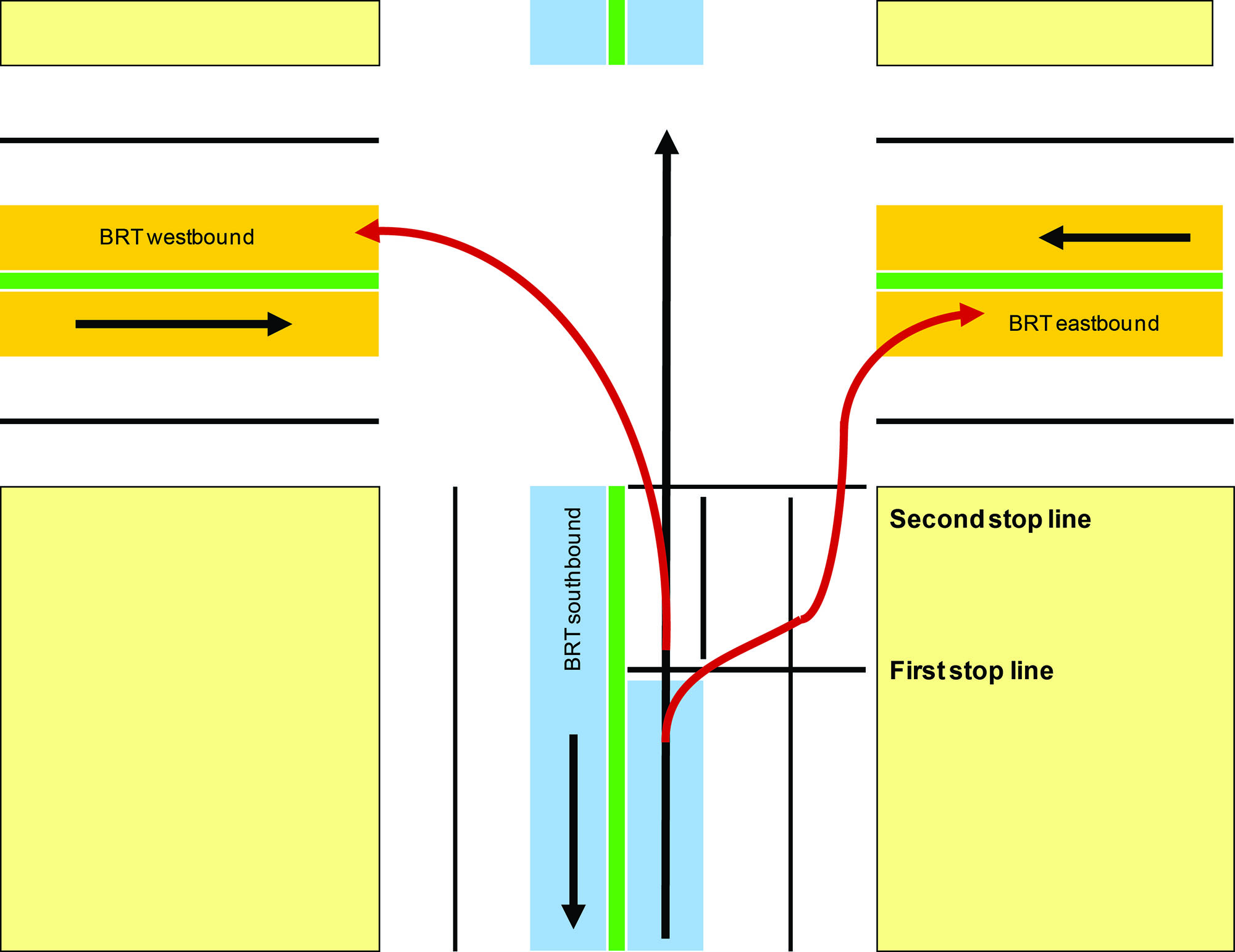
A signal system can be utilized to give BRT vehicles a head start on turning movements prior to private-vehicle turning movements. In this case, a dual traffic signal is utilized for each direction of travel. One traffic signal is located at the intersection, and another traffic signal is located approximately 30 to 50 meters prior to the intersection. At the traffic signal prior to the intersection, the BRT vehicles on the busway would receive a green signal of approximately 10 seconds prior to the green signal for the mixed traffic (Figure 24.58). During this head start, the BRT vehicle would be able to exit the busway and cross to the other side of the street. This is the equivalent of having eight stages and, besides the same problems with congestion in mixed traffic, a BRT vehicle that arrives in the middle of the green phase will be blocked by cross-traffic-turning cars and block eventual vehicles behind it. Figure 24.59 shows an example of pre-signal without BRT turning; it is used as a way to allow mixed traffic turn cross-traffic when the roadway width is constrained.
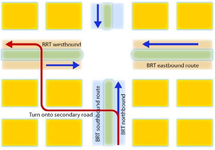
24.6.3BRT Turning Movements Prior to the Intersection
To avoid having a special BRT turning phase in a main intersection, an alternative is to create a special bus-only turn (this is as good for left turns as for right) phase at an intersection before a major intersection where there is less crossing demand than in the main crossing corridor, or no demand at all (Figure 24.60). For a few blocks, the BRT vehicle will operate on secondary streets (in mixed traffic or in a dedicated lane) until it rejoins the busway. This option requires the availability of usable secondary streets and consideration regarding the placement and use of stations by turning routes (not to move it too far from the origin/destination of many trips on the other side of the main intersection).
24.6.4Convert Cross into a Roundabout
If two crossing corridors happen to be two broad highways, enough right-of-way may be available to convert a standard four-phase intersection into a two-phase signalized roundabout. This is a clever alternative that should be remembered, as in many developing-nation cities, such right-of-way is available but underutilized.
The exclusive BRT busway terminates approximately 50 meters prior to the intersection with the BRT vehicles entering mixed traffic at that point. This approach essentially turns the junction into a grid of one-way streets. It requires a fairly large amount of right-of-way at the junction.
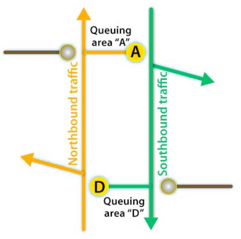
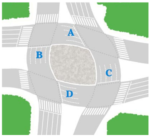
Figure 24.61 indicates how the junction between two major boulevards can be turned into a two-phase traffic circle by creating a kind of mini-grid of one-way streets. At low traffic volumes, the BRT buses enter mixed traffic prior to the intersection. A series of queuing areas (marked as “A,” “B,” “C,” and “D” in the figure) help stage vehicle flows through the roundabout. These areas are referred to as “waiting boxes.”
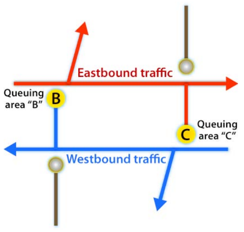
Figure 24.62 outlines the vehicle movements for the first signal phase for this roundabout conversion. This example is given from the perspective of a British-style road configuration. All eastbound BRT vehicles and mixed-traffic vehicles that are making right-hand turns would pass through the intersection and queue in area “C” at a traffic light. All east- and westbound traffic can proceed straight. All vehicles making left-hand turns can proceed. All westbound traffic would pass through the intersection and queue in area “B.”
In the second signal phase, all northbound and southbound traffic can proceed straight, all left-hand turns can proceed, and all right turning traffic would queue in areas “A” and “D” (Figure 24.63).
This solution will work up to the point where the amount of space in areas “A,” “B,” “C,” and “D” is sufficient to accommodate all the turning traffic. The required and available space are discussed in Box 24.2.
Opposite of the rule to increase capacity, the cycle on a signalized roundabout of this type should be short, so the queueing box can handle volumes (manual operators must be very careful when handling these intersections, keeping an eye on the queueing boxes to decide when to alternate to the next phase). Other alternatives of busways through roundabouts are discussed in the next section.
Box 24.2 Required and available space for queueing boxes:
For the purpose of evaluating queueing space, we consider that:
- The amount of road space that a passenger car practically uses is 15 square meters; this includes some distance kept between vehicles to separate them from each other when queueing at the traffic light (\( \text{Area}_\text{pcu} = 15 m^2\));
- The amount of road space needed for a 12 meter-bus to queue is 30 square meters, therefore its equivalence factor is 2.0, i.e., one 12 meter-bus uses twice the space a pcu;
- An articulated BRT vehicle has an equivalent factor of 3.5 pcu;
The available area capacity and the required area (or demanded area) to transform a cross into a roundabout are:
Eq. 24.24
\[ \text{Available Capacity}_\text{queue box} = {\text{Area}_\text{wait-box} \over \text{Area}_\text{pcu} } \]
Where:
- \( \text{AvailableCapacity}_\text{queue box} \): Number of cars that fit in wait box (in pcu);
- \( \text{Area}_\text{wait box}\): Amount of space in the wait box (either "A", "B", "C" or "D" in Figure 24.61);
- \( \text{Area}_\text{pcu} \): Amount of road space a passenger-car uses 15 m2 (it should be expressed in the same unit of \( \text{Area}_\text{wait box} \)).
Eq. 24.25
\[ \text{RequiredCapacity}_\text{wait box} = \text{Flow}_\text{left turn} * \text{Time}_\text{cycle} \]
Where:
- \( \text{RequiredCapacity}_\text{wait-box} \): Number of cars that need to fit in wait box (in the same unit the numerator of the measure described below, normally pcu);
- \( \text{Flow}_\text{left turn} \): Number of vehicles that turn left during the peak (normally expressed in pcu/hour, see basic concepts of this chapter);
- \( \text{Time}_\text{cycle} \): Time duration of a complete traffic light cycle during the peak (normally expressed in seconds, so here the same unit of the flow above needs to be converted, dividing the value by 3,600).
In order for the configuration to function, the available space capacity must be equal or greater than the required capacity.
Example
The following scenario provides an example of calculating the required and available capacity of the proposed roundabout queuing space:
- Turning movement = 540 pcu/hour = 0.15 pcu/sec;
- Cycle time = 90 sec.
Required capacity = 0.15 * 90 = 13.5 pcu
- Unitary pcu space = 3 m * 5 m = 15 m2;
- Length = 30 m;
- Width = 12 m.
Available capacity = (30 m * 12 m) / (15 m2/pcu) = 24 pcu
In this case, the available capacity is greater than the required capacity (24 pcu ≥ 13.5 pcu), so the proposed roundabout conversion could function.
Considering the Figure 23.61, when the number of mixed traffic vehicles and BRT vehicles rises to the point that areas “A,” “B,” “C,” and “D” are too small to accommodate them all, turns should be restricted for mixed traffic but not for BRT vehicles. Effectively, the queuing areas “A,” “B,” “C,” and “D” would be reserved for BRT vehicles.