24.10Grade Separation
Conflict can and should be handled constructively; when it is, relationships benefit. Conflict avoidance is not the hallmark of a good relationship. On the contrary, it is a symptom of serious problems and of poor communication.Harriet B. Braiker, psychologist, expert on stress management, 1948–
Grade separation brings many benefits from the perspective of travel time savings by raising intersection capacity for both BRT vehicles and mixed traffic vehicles. But the infrastructure can be costly, depending on local circumstances. In many instances, the time savings to BRT customers and to private vehicles will fully justify the added infrastructure costs, but limited capital resources will typically constrain infrastructure expenditures.
24.10.1Criteria for Grade Separation
In all of our BRT studies to date we have never really had to resort to a single flyover, meaning that there were always solutions to guarantee BRT operations that would reduce overall current travel times with the available space. In other words: without resorting to grade separation, solutions are likely to be found where the advantages to public transport customers are greater than the hindrance to private vehicle users.
Nonetheless, when the capacity of a four-phase intersection is reaching saturation (more than 450 vehicles/lane/hour in 180-second cycle times), it is fairly typical for engineers to suggest the construction of a flyover or an underpass that allows straight movement for one main road (two of the twelve movements), while all other movements remain at the same level. Such general inclinations often lead toward a political understanding that flyover constructions along the BRT corridor are necessary. Besides that, a corridor project usually has to deal with existing flyovers.
The introduction or existence of flyovers or underpasses along the corridor requires special treatments for BRT systems, but they represent an opportunity to dramatically improve BRT vehicle operation. Exclusive busway use of a flyover is a successful technique used in several existing BRT systems despite its potential major adverse visual impacts, which are highly undesirable from an aesthetics standpoint in cities and urban areas.
An ideal separated-grade solution should only let low intensity intersections remain (low enough to not require traffic lights). If it removes mixed traffic and BRT intersections, then it is best to keep BRT at the grade where access is facilitated, likely to be street level with at-grade crossing.
If the grade-separation solution will not eliminate all conflicts, the first option is to use grade-separation infrastructure for BRT usage and exclusively for BRT if needed.
While the discussion in this section is concentrated on flyovers as a means of grade separation, underpasses are frequently the preferred option from an aesthetics standpoint. Generally, the cost of a busway on a flyover will be at least ten times the cost of a normal at-grade busway (per kilometer). The cost of a busway in an underpass will be similar to that of a flyover unless there are adverse subsurface conditions such as the presence of services (utilities), high water tables, or hard rock conditions that may result in underpasses not being technically or economically feasible.
24.10.2Station Location with Grade-Separated Solutions
If the grade-separated solution design maintains BRT lanes through intersections, the same concerns discussed without grade separation about queue blocking the stations apply. When a BRT lane is grade separated, hindering the station is not a concern, but effective pedestrian access becomes a major issue.
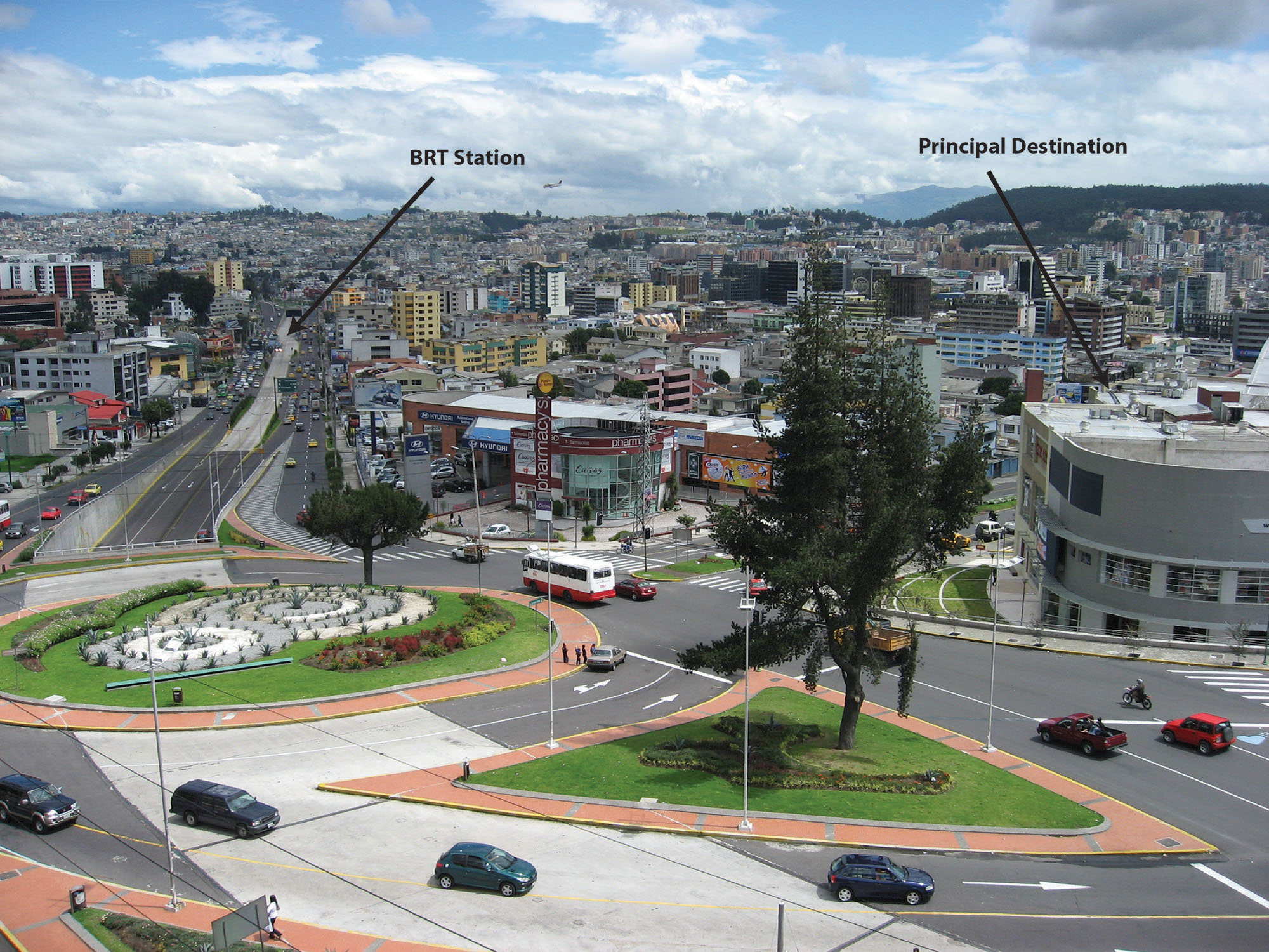
In most instances (ramp of 3 percent and headroom of 4 to 5 meters), grade separation will require placing the stations more than three hundred meters away from the intersection. This siting restriction will add walking time for customers travelling between the station and the intersection and nearby destinations adjacent to the area. Quito’s Central Norte line uses grade separation quite effectively with tunnels whisking BRT vehicles through congested intersections. However, the tunnels also imply that at important destinations, such as the Plaza de las Américas, the closest station is a considerable distance away (Figure 24.74). Thus, for the likely high number of customers using this busy area, the time savings from the grade separation can essentially be lost due to the longer walk.
As an alternative to obtain intersection efficiency (with time savings that serve all customers through the section) at the cost of a convenient station location (that serves local-specific customers), it is possible to place the station beneath or above the intersection. The Metro Center station of the Washington Metro exits directly into the basement floors of commercial shops. In such cases, though, accessing ground-level shops and offices will require a grade transfer for customers, implying either stairs, escalators, and/or elevators.
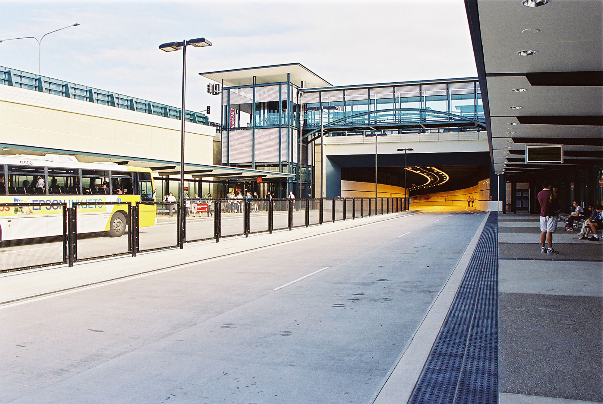
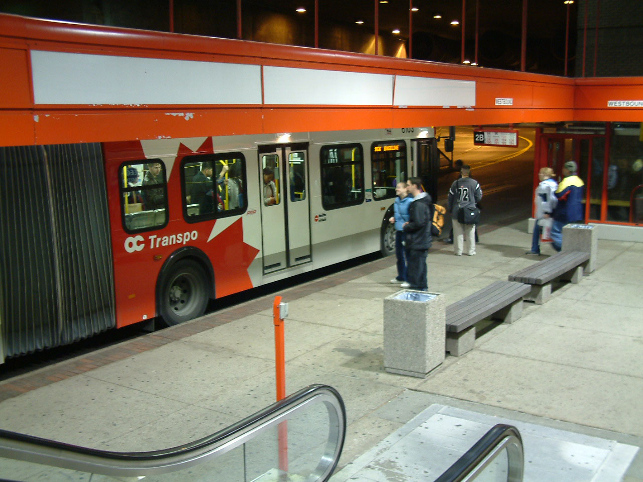
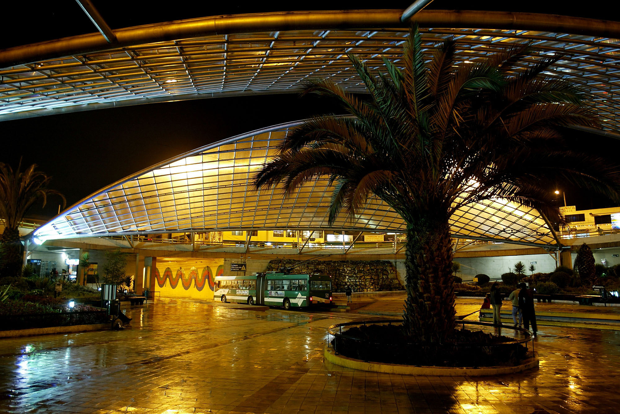
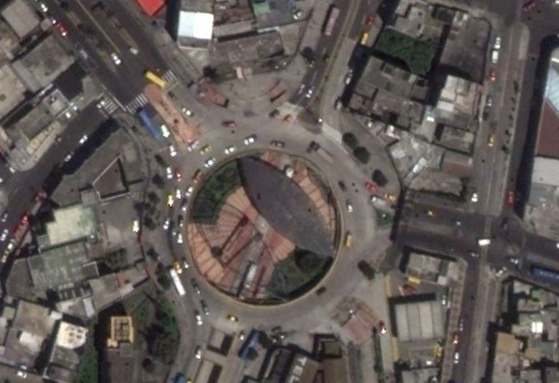
Both the Brisbane and Ottawa BRT systems site stations at the tunnel level. In Brisbane, the station is just before the tunnel and thus provides good customer access to local destinations (Figure 24.75). In Ottawa, the station connects directly to a commercial shopping center (Figure 24.76). Further, in the case of Ottawa, the tunnel station nicely protects customers from the harsh winter weather. Quito also has achieved great success with its Villa Flora station, which goes beneath a heavily trafficked roundabout on Maldonado Avenue (Figure 24.77).
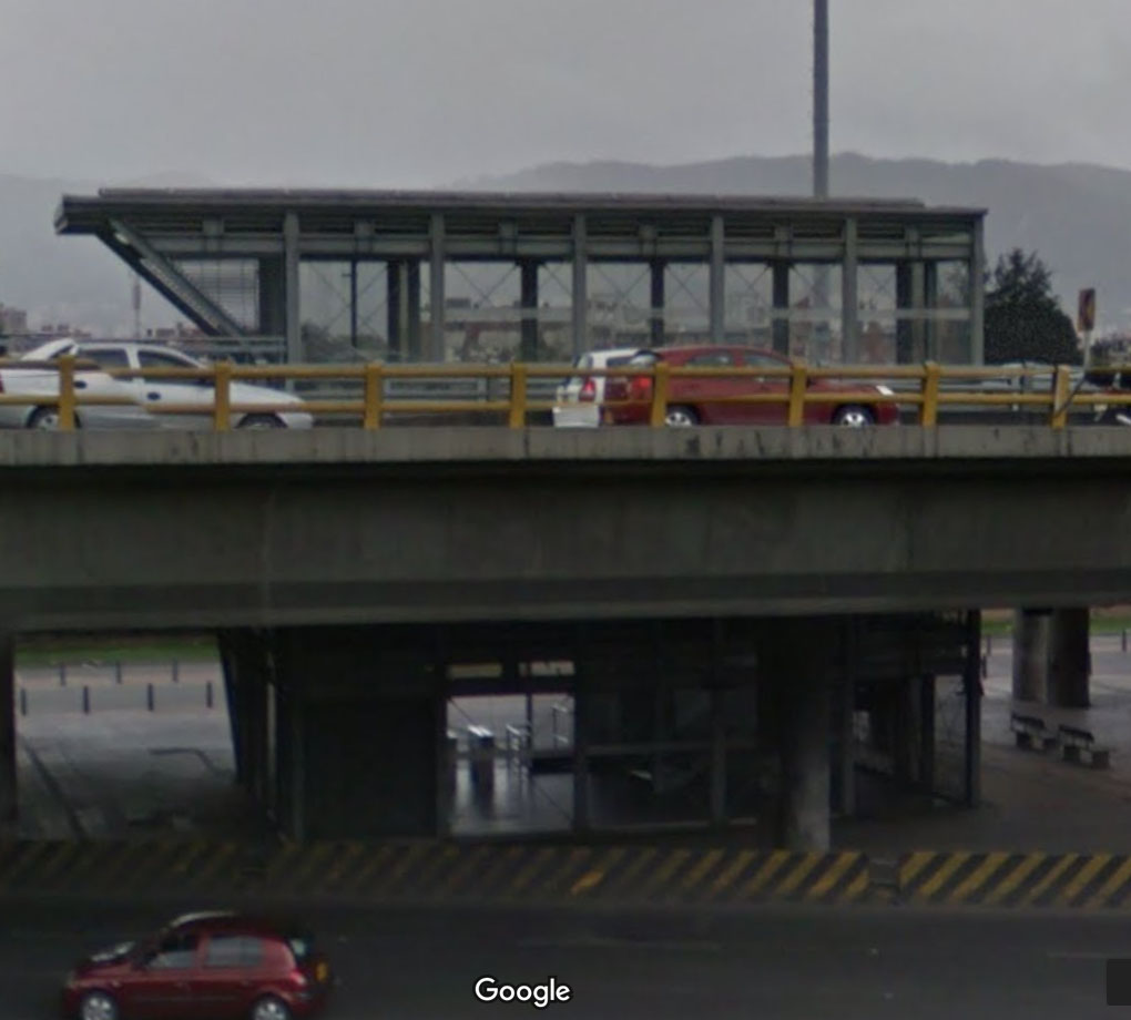
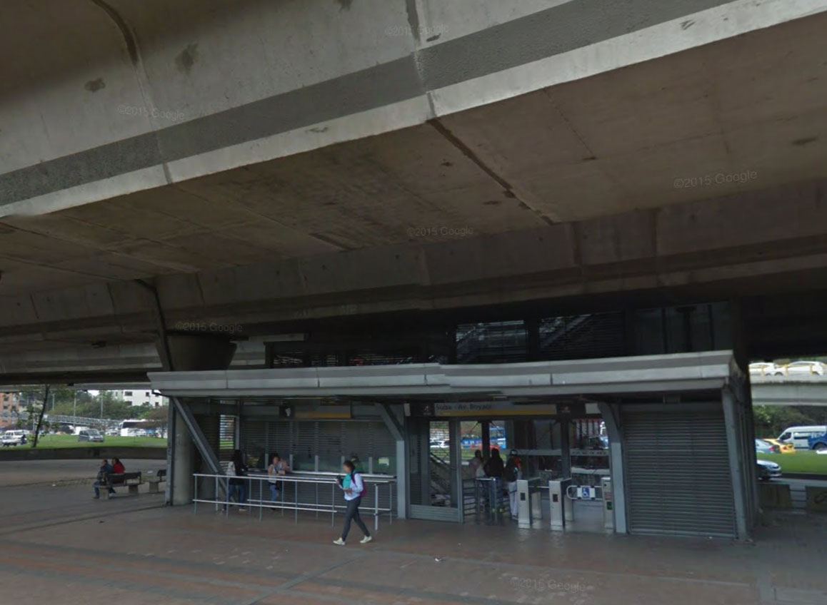
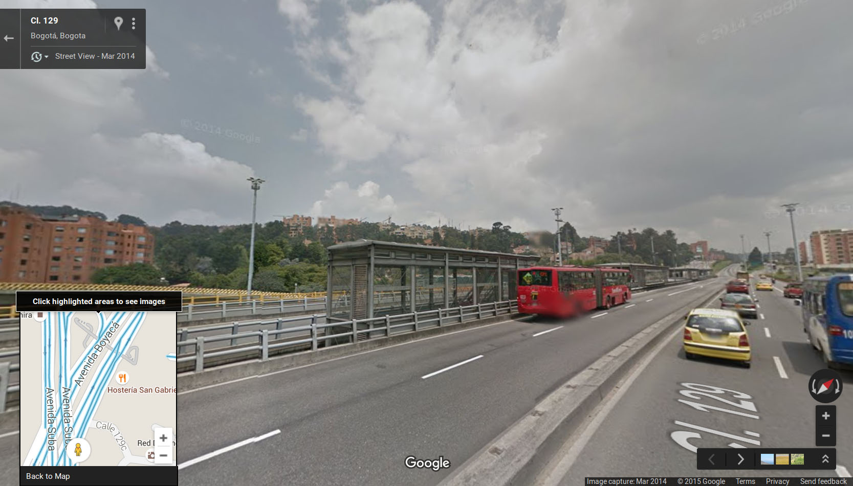
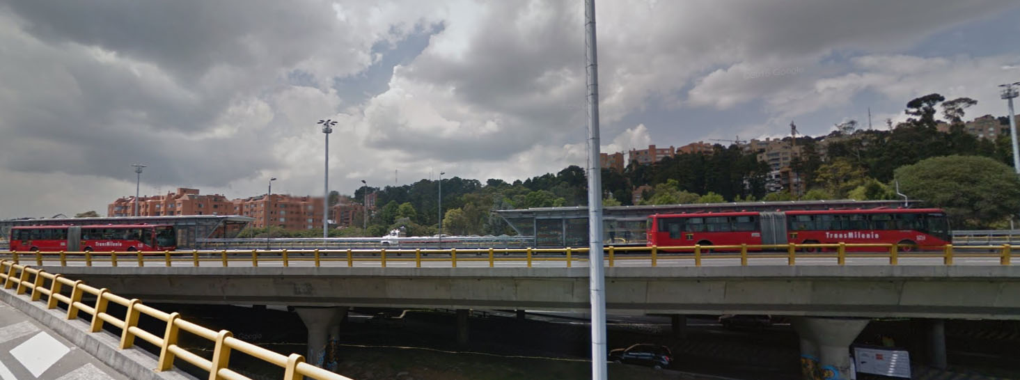
Effective pedestrian access as well as visually neutral solutions can be designed. For TransMilenio Phase II’s “Avenida Boyacá” station along the Avenida Suba Corridor, the solution was to locate the station above Avenida Boyacá, level with the flyover. Pedestrians access the platform via an elevator from a small pedestrian plaza where fares are collected. This solution allowed for the strategic location of this station, which will make future transfer points on the projected Avenida Boyacá closer to each other. Ultimately, the implementation of solutions of this sort will depend on budgetary constraints.
24.10.3Restricting Turning Movements Together with Grade Separation
As said in the introduction to this section, unless all vehicle intersections are eliminated from the BRT lane by the separated-grade solution, the first option is to consider grade-separation infrastructure to be used by the BRT. In such cases, the concern is to determinate if cost of a separated-grade station can be afforded and is justified by the time saved by users of that station. This cost consists of the infrastructure and/or the time losses generated to private vehicle users that will lose a second or a third lane on the separated-grade infrastructure (and if it is politically affordable, too).
A second possibility is to direct BRT vehicles to the flyover in mixed traffic (see Section 24.7: Merging with Mixed Traffic in Narrow Sections), which will result in stations being far from the intersections. Additionally, this configuration can be particularly problematic if there is a connecting BRT corridor running on the perpendicular street below the flyover or above the underpass.
The third possibility is building the flyover on the road perpendicular to the BRT corridor. In this case, the flyover does not introduce any special difficulty in relation to the (same-level) intersection already discussed and if it cannot eliminate the intersection with mixed traffic, it can certainly alleviate the intensity and the number of conflicts, increasing the BRT green time (as this subsection will lead us to conclude by analyzing the following last possibility).
The last possibility is that the flyover is designated for mixed traffic alone and BRT remains on the street level. As the others do not create intersection with BRT, this fourth possibility is only of interest for the remainder of this subsection (though all four must be considered when evaluating benefits).
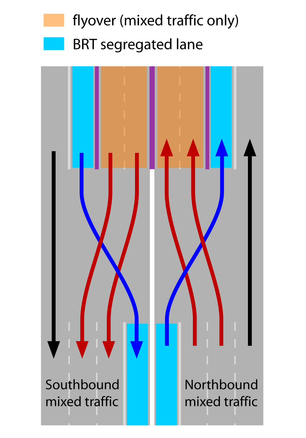
If a single flyover in the median is built, the BRT vehicles in the median will have to cross the mixed traffic going onto the flyover. This scenario creates either the need for a new signalized intersection prior to the flyover, or a merging lane where the BRT buses and mixed traffic can cross, introducing possible delay and confusion for both the BRT system and the mixed traffic. Figure 24.82 shows the conflict.
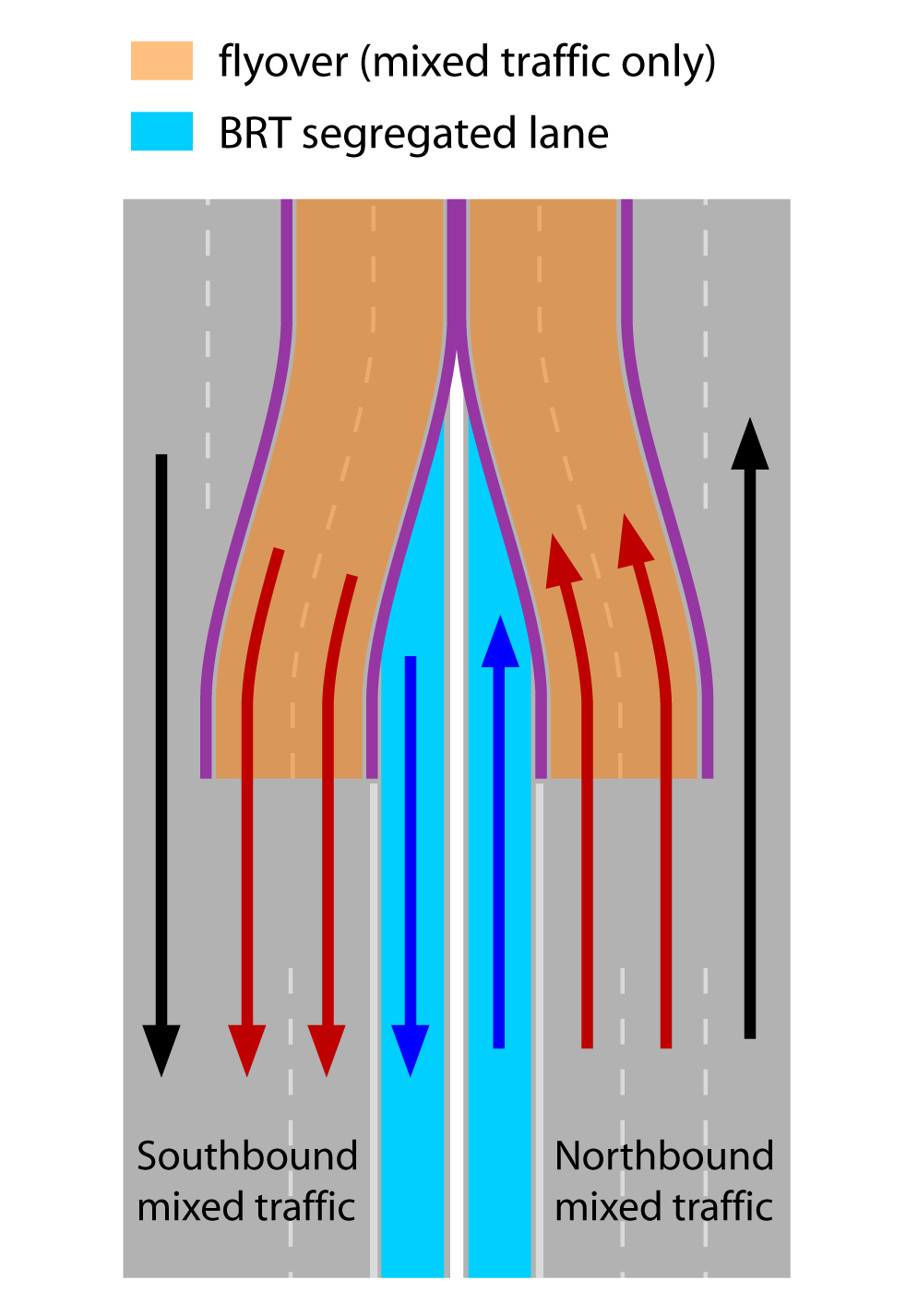
If two separate access lanes are constructed for the flyover, one for each traffic direction, it is possible to leave a space between them for the BRT system to continue along the surface as in Figure 24.84.
In this configuration, the BRT will intersect the crossing street under the flyover, so we must consider the alternatives of Section 24.5 with the introduction of the flyover to reduce the number of phases. We present the results of a scenario in which BRT has a green signal with the insertion of a grade-separation infrastructure of two lanes per way (Figures 24.87 to 24.89), maintaining the assumptions in subsection 24.5.4: volumes are equal in all approaches, right and left turns each represent 25 percent of the demand and no U-turns are allowed (therefore 50 percent of traffic is straight), no pedestrian-only phases are required (it is possible to cross the intersection with the given phases), and 90 seconds is still the cycle time of reference.
Although the flyover can cause the impression that four new lanes are created, no mid-block extra width is created (Figures 24.82 and 24.84). Eventually the intersection under the flyover can have some extra width, but usually two lanes near the median are used to place the supporting structure of the flyover, so there is in fact only two extra lanes in the intersection as a whole. Below, we will evaluate the uninterrupted flow in these four lanes.
In our example, the first problem with the mixed traffic comes at the point of flyover access, as half of the traffic has turning intentions, and if permitted to do this, turns at the intersection (under the flyover or above the tunnel) are not enough. Or, if the detours start after the ramp begins, the single lane given for mixed traffic to stay on the flyover is not enough. Widening or sharing space with BRT is required. The solution presented in Section 24.7 does not apply here without further complications as there are two downstream sections (overpass and ground) to be managed. Designing with the assumption that the intersection will not congest because the design is good for the forecast demand is simply naive: when it comes to cars, all the designer can expect is to improve capacity, and sooner or later congestion will return. Given our goals, placing BRT in a shared space with cars in this potential bottleneck is a bad proposal.
So the maximum capacity we present for mixed traffic is still subject to the intersection below the flyover working well. If it gets congested, access to the flyover will also be congested. For proper comparison with the solutions without grade separation, and also because the effective access to the “intersection plus flyover” set has three lanes for mixed traffic, we present the results per lane, assuming each intersection approach has three lanes, as detailed below:
- Average lane capacity: the average of the mixed-traffic lanes’ capacity that would be measured at the stop lines approaching the main intersection. On the presence of a flyover, mixed traffic parallel to the BRT’s approach is considered three lanes, but only two of these were effectively used to balance the traffic sign);
- Overall intersection capacity per lane: in the loop configuration, vehicles pass twice through stop lines in order to execute a cross-traffic turn, and the second pass does not count toward this capacity, but rather it is the same result described in the “average lane capacity” above, except that it does not count the second passage of the same vehicle across the intersection.
- Total throughput with flyover and auxiliary intersections per lane at intersection: this adds in the flows that were completely diverted away from the main intersection (detours and flyover) as if they were effectively passing through the intersection. By bringing the value to the number of lanes of the intersection, this presents a practical estimate of how much the capacity of the main intersection can be pushed to benefit from using the auxiliary ones and flyover as a whole.
Options where the detours are below the flyover assume that the height clearance makes it possible, which is not always the case. Access ramps to and from perpendicular streets may also be taken into account in order to make turning detours on the flyover possible.
Table 24.5Flyover Capacity Examples
| Option | Cycle Time (seconds) | Phases | BRT Direction Straight Flow | BRT Direction Curb-Side-Turn Detour | BRT Direction Cross-Traffic-Turn Detour | Perpendicular Direction Curb-Side-Turn Detour | Perpendicular Direction Cross-Traffic-Turn Detour | Figure | BRT Green Time (seconds) | Average Lane Capacity (pcu/hour) | Overall Intersection Capacity per Lane (pcu/lane) | Total Throughput with Auxiliary Intersections per Lane at Intersection |
|---|---|---|---|---|---|---|---|---|---|---|---|---|
| A | 90 | symmetrical | - | - | - | - | Fig. 24.35 | 22 | 395 | 395 | 395 | |
| A1 | 90 | symmetrical | on flyover | - | - | - | - | 16 | 329 | 329 | 439 | |
| E | 90 | 3 | - | - | detour | curb-first | Fig. 24.38 | 43 | 496 | 496 | 567 | |
| E1 | 90 | 3 | on flyover | - | - | detour | curb-first | 43 | 355 | 355 | 567 | |
| I | 90 | 2 | detour | curb-first | detour | curb-first | 41 | 819 | 819 | 1092 | ||
| I1 | 90 | 2 | on flyover | detour | curb-first | detour | curb-first | Fig. 24.87 | 27 | 729 | 729 | 1458 |
| I2 | 90 | 2 | on flyover | detour | loop onto flyover | detour | curb-first onto flyover | Fig. 24.88 | 49 | 547 | 547 | 875 |
| J | 90 | 2 | - | loop | - | loop | 41 | 819 | 655 | 655 | ||
| J1 | 90 | 2 | on flyover | - | loop | - | loop | 39 | 691 | 518 | 691 | |
| K | 90 | 2 | detour | loop | detour | loop | 41 | 819 | 614 | 819 | ||
| K1 | 90 | 2 | on flyover | detour | loop | detour | loop | 35 | 703 | 469 | 937 | |
| K2 | 90 | 1 | on flyover | detour | loop onto flyover | detour | loop onto flyover | Fig.24.89 | 10 | 1520 | 1216 | 1216 |
| K3 | 60 | 1 | on flyover | detour | loop onto flyover | detour | loop onto flyover | Fig.24.89 | 10 | 1380 | 1104 | 1104 |
| K4 | 45 | 1 | on flyover | detour | loop onto flyover | detour | loop onto flyover | Fig.24.89 | 10 | 1240 | 992 | 992 |
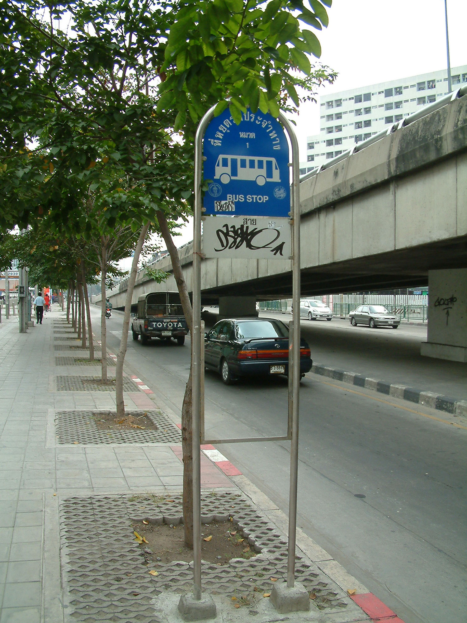
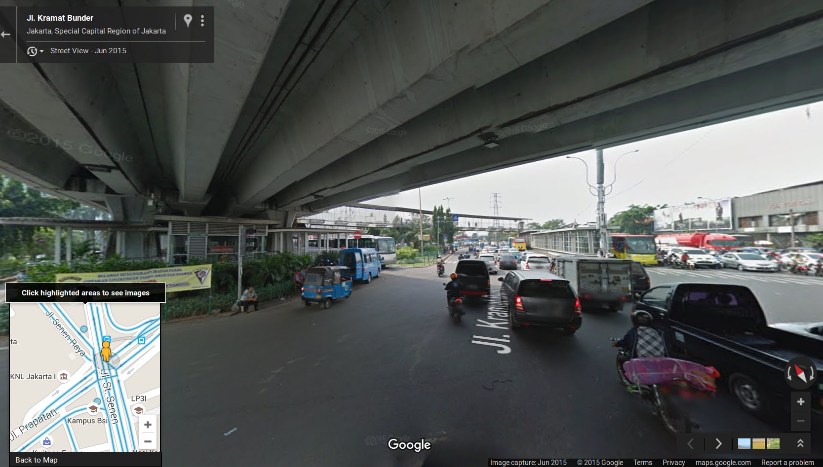
Option A1 is fairly common with conventional bus services (as in Bangkok, Figure 24.85) and BRT (as in Jakarta, Figure 24.86). Mixed-traffic vehicles have access to the flyover and thus are given a substantial priority at the intersection. By contrast, public transport vehicles servicing the intersection area are often mired in heavy congestion. There is limited benefit of using a flyover or underpass if a four-phase signal timing is maintained. In our established scenario, the overall increase in the whole intersection capacity is quite small, with the capacity only rising from 395 pcu/lane/hour to 439 pcu/lane/hour.
Using three phases, moving from option E to option E1, curiously adds no benefit with the use of the flyover. Even with 50 percent of the traffic being diverted to the flyover and the reduction of the approach parallel to the BRT from three to two lanes (while one lane is used for cross-traffic turns), only one lane is able to process both curbside turns, and cross-traffic turns from the perpendicular direction all result in the same relative green distribution with or without the flyover. But mixed traffic using only one lane for such a long phase (the same as the BRT phase) reduces the intersection’s overall capacity substantially (71.5 percent). Adding the flow on the flyover (60 percent) results in exactly what is coincidentally the same overall capacity as having an intersection plus flyover.
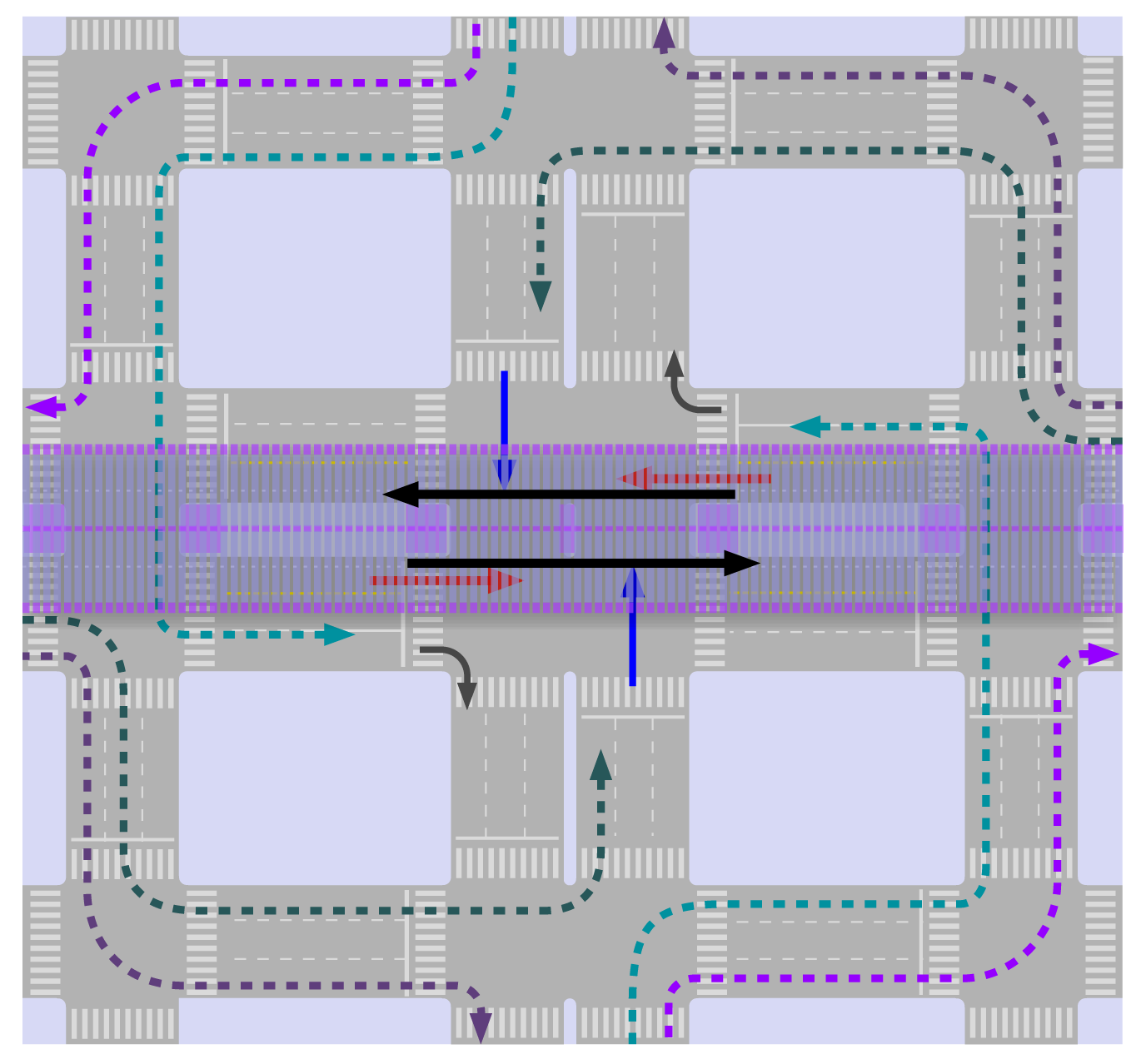
Without a flyover, the best observed configurations consist of the following options: (Option I from Table 4.5, Figure 24.87) doing all detours on the curbside parallel street to turn onto the desired direction once the other street is reached, letting only straight flows in the perpendicular street and in the flyover is the Option (I1) that results in larger capacity for mixed traffic and not coincidentally the shortest green time for the BRT (27 seconds), except for the four-stage alternative (A1). That happens because the only conflict left at the main intersection is perpendicular straight flow (in three lanes) against perpendicular cross-traffic turn (in two lanes). Having 63 seconds of red time may not be unbearable for a low frequency BRT, but it will almost certainly not allow a station to be positioned between the two intersections (the main and the auxiliary), since the resulting saturation for the conjunct station plus intersection will be much higher than that of a station alone.
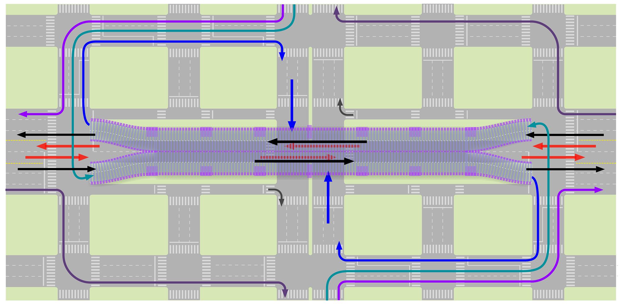
Applying the same scheme, but using the flyover (Option I2, Figure 24.88), moves all the conflicts to the secondary intersection, which ends up being the capacity limiting element for the conjunct. As there are only two lanes in the flyover to handle the straight flow plus the cross-traffic flow from both directions (i.e., double flow in two-thirds of lanes), its result is worse than some alternatives without a flyover.
For the clovelike alternatives (Options K, K1, K2), adding the flyover and maintaining the loops on the ground (Option K1) raises overall capacity for the system by 15 percent (comparing with option K). Making detours in auxiliary streets to take the bridge (Option K2, figure 24.89) will make it look like a “real-clove interchange” and, except for the BRT, there would be no intersection (pedestrian phase is required now). Therefore, the BRT phase would be the minimal 10 seconds and an equivalent average capacity of lanes would be 1,520 pcu/hour. Nevertheless, as all vehicles willing to do cross-traffic turns at the intersection use it twice, this is equivalent to “only” 1,216 pcu/hour.
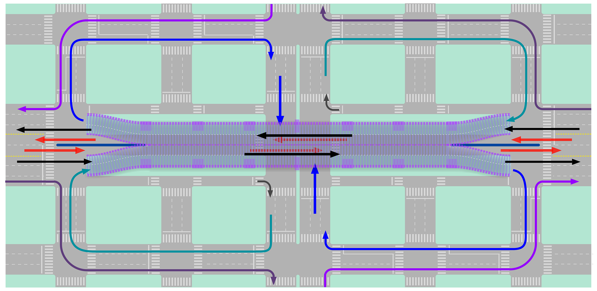
The fact that this situation is equivalent to a BRT cross only, the cycle time can be reduced to BRT maximum red time requirements. If this requirement is 50 seconds, then the intersection cycle can be 60 seconds (Option K3) and equivalent overall capacity is reduced to 992 pcu/hour/lane. If it is 35 seconds (maybe enough to bring the station 20 meters from the intersection and fit under the flyover), the cycle has to be 45 seconds (Option K4) and capacity is further reduced to 992 pcu/hour in our example.
Although generic, the assumptions of this exercise are quite common, so there is a strong suggestion that:
- Without grade separation, reducing signal phases to two can provide solutions as good as many grade-separated solutions in terms of capacity for mixed traffic and results in better BRT green times than grade-separated solutions.
- To prioritize BRT green times and meaningfully increase capacity, the use of separated-grade solutions must be cleverly associated with turn restrictions, and the best solutions are obtained if the flyover is on the perpendicular road (had that been the case of options I1 and K2, green times for the BRT would be respectively 54 and 76 seconds in a cycle of 90 seconds).
As mentioned before, an intersection cannot be analyzed in isolation. Optimum results are usually obtained when vehicle movements are analyzed along the corridor and the entire extended area surrounding the intersection.
24.10.4BRT Turning with Grade-Separated Solutions
Separated-grade infrastructure can also be used to provide the dedicated turns for the BRT. For heavy traffic corridors where free-flow turning is required to avoid breaking down the system, the time savings certainly justify the costs.
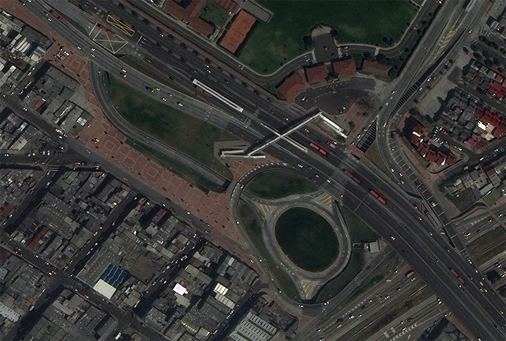
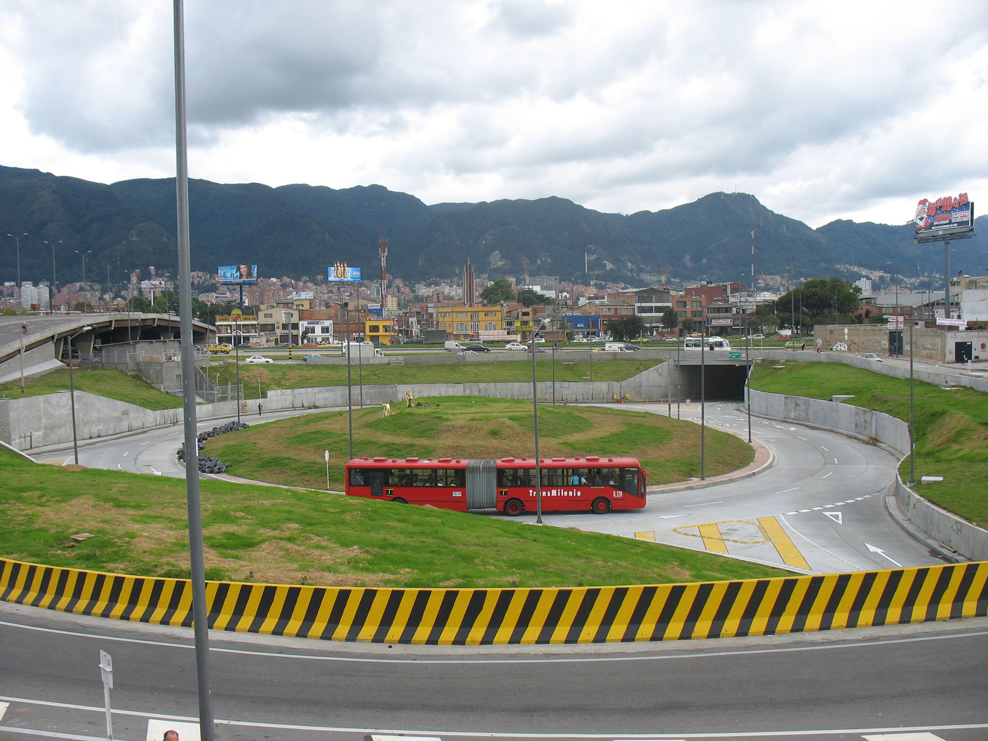
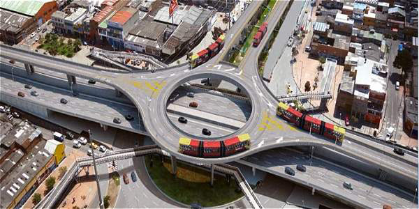
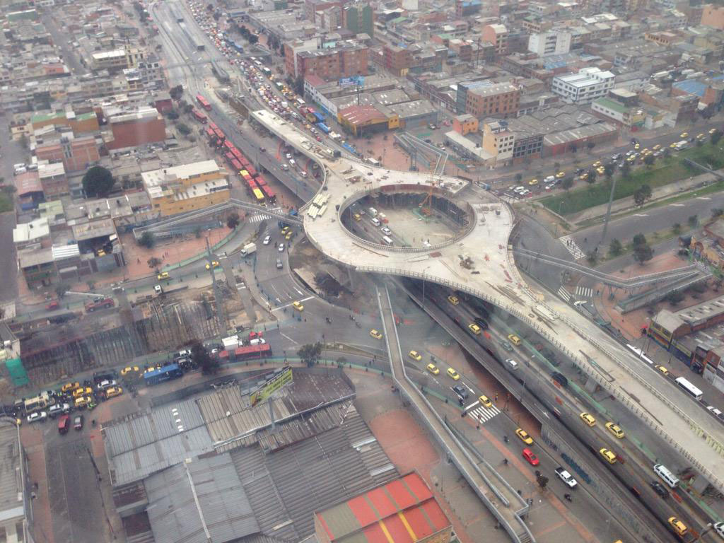
Bogotá utilizes grade separation to provide dedicated turning infrastructure to BRT operations, such as overpasses and underpasses that link the corridors of 80th Street and Norte-Quito-Sur to an exclusive BRT roundabout (Figures 24.90 and 24.91), as well as provide an exceptional BRT-only third-floor roundabout completed in 2015 to guarantee that the interchange in Norte-Quito-Sur and Calle 6 has no delays (Figures 24.92 and 24.93).
24.10.5BRT through Roundabouts with Grade-Separated Solutions
Constructing a busway underpass that goes below the roundabout and avoids all conflicts with mixed traffic—and thus promotes time savings for both BRT and mixed traffic—is also a possibility, as the examples from Quito with good and bad station locations show (Figures 24.74 and 24.94).
A flyover is also a possibility, but the design of an aesthetically acceptable solution is very challenging. With the exception of the exceptional third-floor roundabout above mixed traffic in Bogotá as mentioned in the previous section, there are no other readily available examples of an aesthetically acceptable flyover.