24.5Restricting General Traffic Turning Movements
No matter how many times you save the world, it always manages to get back in jeopardy again. Sometimes I just want it to stay saved! You know, for a little bit? I feel like the maid; I just cleaned up this mess! Can we keep it clean for . . . for ten minutes!Mr. Incredible (Craig T. Nelson), The Incredibles, 2004
The overall capacity of the intersection is given by the sum of the capacity of each approaching lane. By its turn, the capacity of each approaching lane is given by the sum of saturation flow of the lane multiplied by the sum of the relative green times of the phases for when the lane is active.
No matter how many phases there are on the traffic light, the sum of relative green for all vehicular phases with relative lost time is constant (if there were no pedestrian phases, it would be equal to one). The initial step to programming traffic lights is to divide this fixed amount among the phases with the general assumptions that (1) a movement not allowed during a given phase will block a lane and (2) that the saturation flow per lane is the same (for turning it can be lower): for any given signalized intersection, if a phase is removed (therefore the movements of that phase are removed) and the green time including the approaches for the movements of the removed phase are included into another phase (both in the same phase), then the overall capacity of the intersection will necessarily increase.
This is empirically clear for a user arriving in a balanced intersection, since a larger number of phases in a traffic light means waiting longer and having a lower share of green time.
Of course it is not interesting to create capacity for movements without demand. The following subsections will discuss alternatives to divert traffic in order to increase capacity by eliminating phases. We will see that in some cases, intersection capacity is still increased even if the demand for some eliminated movements, namely cross-traffic turns, are forced to pass over the intersection twice.
Widening the intersection can be of great assistance, but doing it alone rarely can achieve the same benefits of reducing phases from four to two. In a relatively normal situation where turning volumes are large enough to the point that after the intersection the straight flow can fit in one less lane than before the intersection (as discussed in Section 24.4.2: Minimizing the Number of Mixed-Traffic Lanes Away from the Intersection), it is possible to narrow the exiting section, allowing the entrance section of the opposite way to be broader (Figures 24.28 and 24.29); the extra width can be useful for mixed traffic, enhancing mixed-traffic capacity, or to allow BRT turning movements where required (see Section 24.6: Allowing BRT Turns).
Box 24.1 Narrowing lanes
Narrowing lanes is a recognized traffic calming measure and a possible way to increase the intersection approach capacity. Even though the saturation flow will be reduced in each lane, if one more lane can be squeezed into the stop line, capacity may increase and a better use of space for queueing may be provided.
Places where congestion is a serious issue may already have addressed regulation that allows using narrow measures, and, if not, public works guidelines have to be changed.
The United States Federal Highway Administration suggests that, despite the desired lane width of 3.6 meters to maximize flow, right-of-way or pedestrian needs may dictate use of a narrower lane width; lane widths below 2.7 meters are not recommended for new design, but in some very constrained retrofit situations on low-speed roadways, lane widths as low as 2.4 meters should be considered where appropriate (Figure 24.30).
24.5.1Eliminating Intersections
The extreme case of reducing phases would only allow for one phase, which would be equivalent to eliminating the intersection itself, clearly increasing capacity.
Thus eliminating intersections along the busway seems at first a good idea. For median-side busways this can be done by simply forbidding cross traffic, while still allowing flow from the transversal street to join the mixed traffic in the corridor at the curbside as in Figure 24.31, providing access to the corridor.
The flaw in adopting such an extreme solution is that eliminating phases is based on diverting traffic demand in favor of the exclusive movements, so its movement can be done with other flows. Eliminating the movement (in this case, crossing the corridor) does not eliminate the demand for it; the movement has to happen somewhere else.
This measure will reduce accessibility when applied without discretion and will concentrate crossing demand in a few locations (Figure 24.32). Before eliminating an intersection, it is necessary to understand which alternative paths the demand will use to cross the corridor and compare the impacts of both situations: if the volumes are low or if the alternatives will not generate more delay to the BRT, then it really is a good idea to eliminate the intersection. Eventually, it will become necessary to create new intersections to split conflicting volume of one intersection into several to increase green times for the BRT.
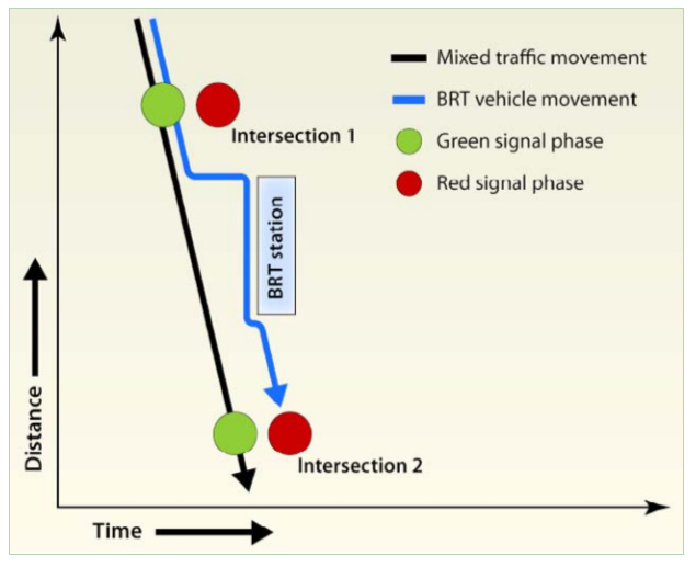
If there are no stations in the surrounding area, then BRT vehicles can pass through several intersections at once if a synchronized signal system is used (see Section 24.1.3: Traffic Signal Concepts and Section 24.3.1 Passive Signal Priority). However, when there are stations between intersections, the BRT vehicle will pass through the green phase at the first intersection and then stop at the station for customer boarding and alighting. By the time the vehicle resumes movement toward the second intersection, the signal phase may have changed to red (Figure 24.33).
But when intersections are too close together in order to optimize the station location relative to them, an assessment has to be made regarding how important the station location is for boarding and alighting customers, the detour forced on mixed traffic close to the station, and to what extent it hinders the whole BRT system due to interference between the station and the intersection. There are three options:
- Close one of the intersections: this generates mixed-traffic detour time and higher cross volumes at other points that may impact the BRT corridor as well;
- Transfer or remove the station: this increases walking time for BRT users of that station;
- Keep station and intersections: this generates delay for all customers in the BRT that pass through the intersection.
Even for normal mixed traffic, having two intersections too close together will sometimes lead to problems of the same nature as discussed in Section 24.4.2: Minimizing the Number of Mixed-Traffic Lanes Away from the Intersection and Section 24.4.3: Minimizing the Recommended Distance between the BRT Station and the Intersection from a Mixed-Traffic Perspective vehicles queued at one intersection will back up to the point where vehicles are unable to clear the previous intersection during a green phase. Equation 24.22 below defines the calculation for the distance above which this type of conflict shall not occur.
Eq. 24.23
\[ D_{i1-i2} \geq 3 * Max(T_\text{green-i1},T_\text{green-i2}) \]
Where:
- \( D_\text{i1-i2} \): Distance in meters between intersection 1 and intersection 2;
- \( T_\text{green-i1} \): Green signal time in seconds at intersection 1;
- \( T_\text{green-i2} \): Green signal time in seconds at intersection 2.
A mixed-traffic lane can generally handle 1,800 vehicles per hour. This quantity translates to two vehicles per second (3,600 seconds in an hour). When vehicles are stopped at a stoplight, the average amount of space they take up is 6 meters; this space includes the vehicle and some space between vehicles. This average vehicle distance means that for each second of time, 3 meters of vehicle-equivalents can be moved through the intersection.
This distance between the intersections guarantees that there is enough space for queueing vehicles, so that it does not happen that the green light is open and there are vehicles stuck in the upstream traffic light. Proper synchronization can reduce this distance to practically zero.
Example
The following scenario is outlined in order to determine whether two intersections 100 meters apart will result in free-flow operation or in congestion:
- Di1-i2 = 100 meters;
- Tgreen-i1 = 50 seconds;
- Tgreen-i2 = 30 seconds.
To determine if the distance between these intersections is sufficient, Equation 24.19 can be applied:
\[ 100 \geq 2.5 * Max(50,30) \]
\[ 100 \geq 150 \leftarrow \text{FALSE} \]
Since 100 meters is less than the required 150 meters, there is not enough space between the intersections.
In the direction from 1 to 2 it is possible (if 2 is red while 1 is green) that vehicles queuing at 2 will back up onto the first intersection and the last 50 meters of queue will be trapped before intersection 1.
In the direction from 2 to 1 it is possible (if 1 green starts the same time the first vehicle from 2 arrives at the intersection), then the last 20 seconds of green in 1 will be useless, since vehicles stop flowing after 30 seconds in intersection 2.
24.5.2Shortening and Eliminating Phases
In this subsection we name traffic diversion models and traffic sign phase schemes as we describe them in order to refer to them in the following text and in the next subsection.
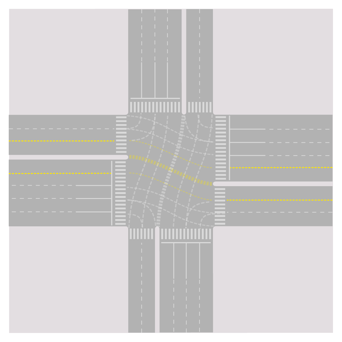
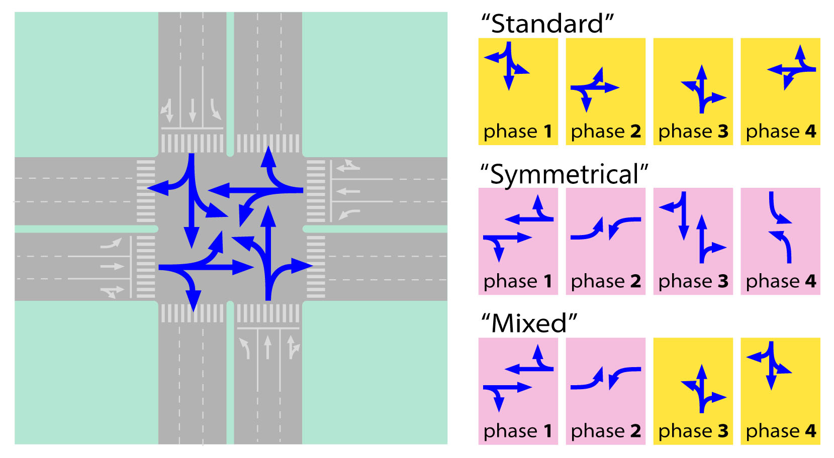
24.5.2.1Typical 4-Phase-Intersection
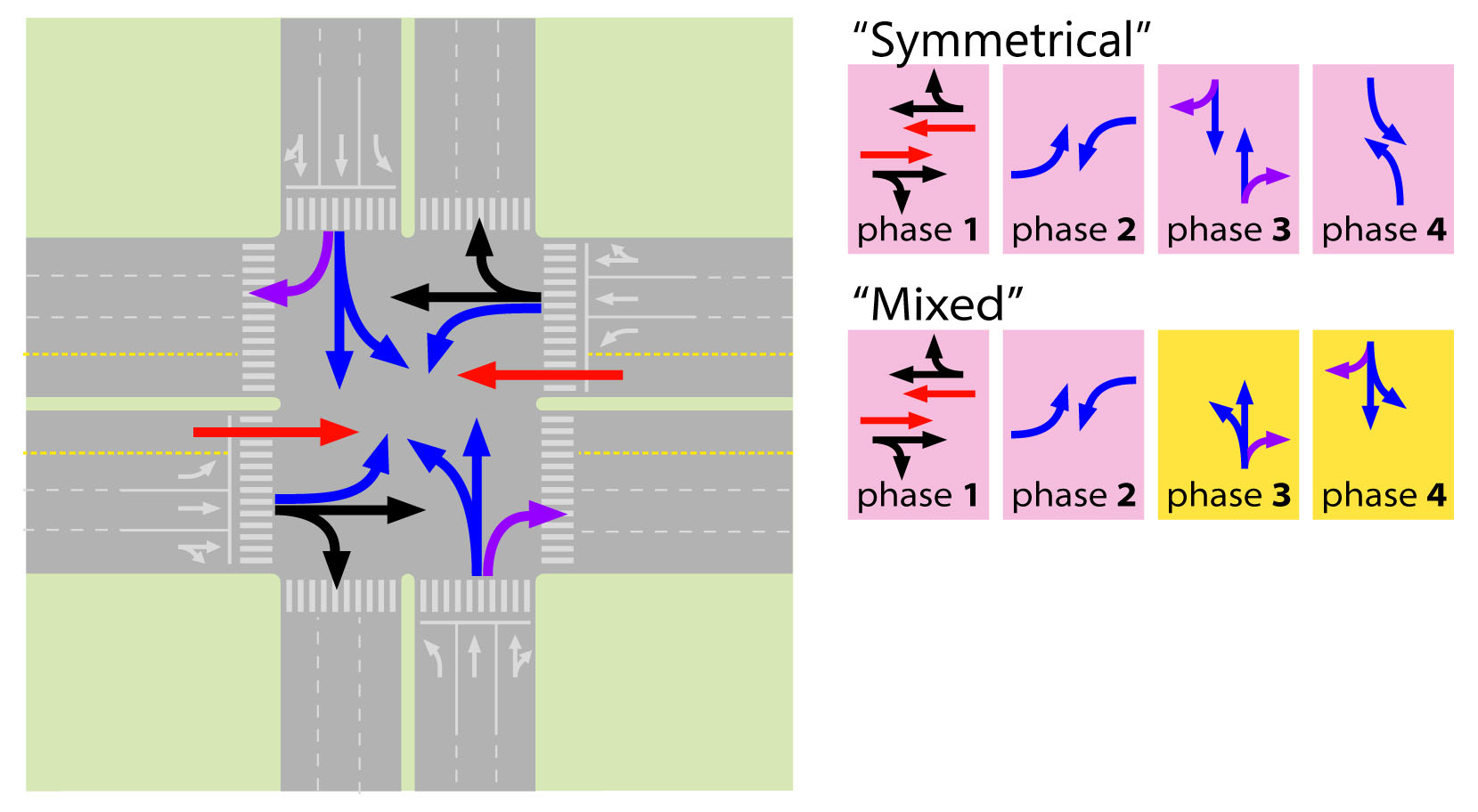
In a typical intersection that allows all movements (Figure 24.34), four phases are required; usually each origin has its phase (“standard-four-phase”) but an alternative scheme with one phase for each direction (two ways) in straight movement and curbside turns, and one phase for each direction (two ways), cross-traffic turn may be used as well, which we will refer to as the “symmetrical phase.”
The standard configuration has the advantage of not requiring dedicated queue space (queue box) for cross-traffic turns and also allow sharing one lane for cross-turn and straight movements (it can be the most median-side or the second closest to it) and let the intensity of the flow variations along the day balance the use of this lane. The symmetrical phases are interesting when cross-traffic-turn flows are relatively low and straight movements are intense in both ways (cross-traffic-turn phase will be short and straight will be long). Our practical experience suggests that symmetrical tends to be better if a clear bidirectional flow exists, but it ultimately requires an assessment of the flows intensity to each application.
A combination of the two is also possible, using cross-traffic-turn phase for one direction, and one phase per origin in the other direction (“mixed-four-phase”).
24.5.2.2Movements Conflicting with BRT
When the BRT has to cross a typical four-stage intersection, the main concern is to increase the green time for the corridor direction. Eliminating phases are likely to be very effective in doing so, but it is important to keep in mind that it is not the primary goal. Eliminating phases in a way that green time is not increased for the BRT approaches will improve only mixed-traffic performance.
To eliminate the phases we must focus on the movements that conflict with the BRT (Figure 24.36) and try to reroute them in such a way that they can cross the corridor in one phase and briefly—that is, providing width to the crossing movement approaches. Providing width to parallel movements is important to improving general traffic, which is also desirable, but not paramount.
For the remainder of the section we will assume that the busway is median-side aligned and that the busway crosses the intersection straight; if the busway is curbside and/or it is turning between perpendicular roads, the same reasoning applies and the same alternatives for detour mixed-traffic movements will be considered, but in a different and appropriated way.
With a median-side BRT, standard-four-phase sign can no longer be applied, as it will conflict with the cross-traffic turn (Figure 24.35), so the symmetrical or the mixed-four-phase has to be used.
24.5.2.3Diverting Curbside Turns
Diverting curbside turns does not remove a phase, but it can free space for queueing and increase capacity for the remaining movements.
Moving curbside turns away from the intersection is usually simple if parallel streets are available (Figure 24.37). It will require a cross-traffic turn in the parallel street corner, which may start to spread the main corridor intersection problems to a broader area. Detouring the curbside flow from the crossing street is particularly interesting because it can leave the width of the whole approach available to conflict movements, reducing the crossing time (red for the corridor) in the same proportion this curbside-turn flow is to the total flow, even if four phases are in use. From a BRT point of view, there is no interest in diverting the parallel curbside flow at the intersection, as it is not a conflicting movement.
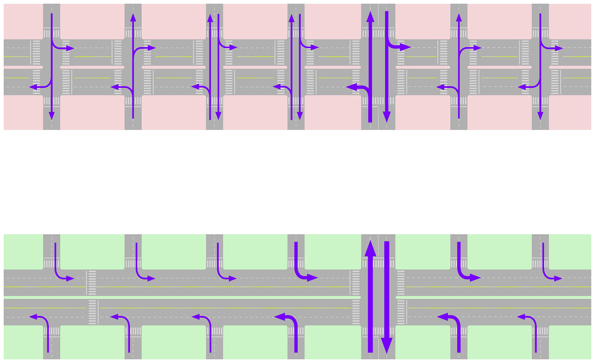
24.5.2.4Diverting Cross-Traffic Turns
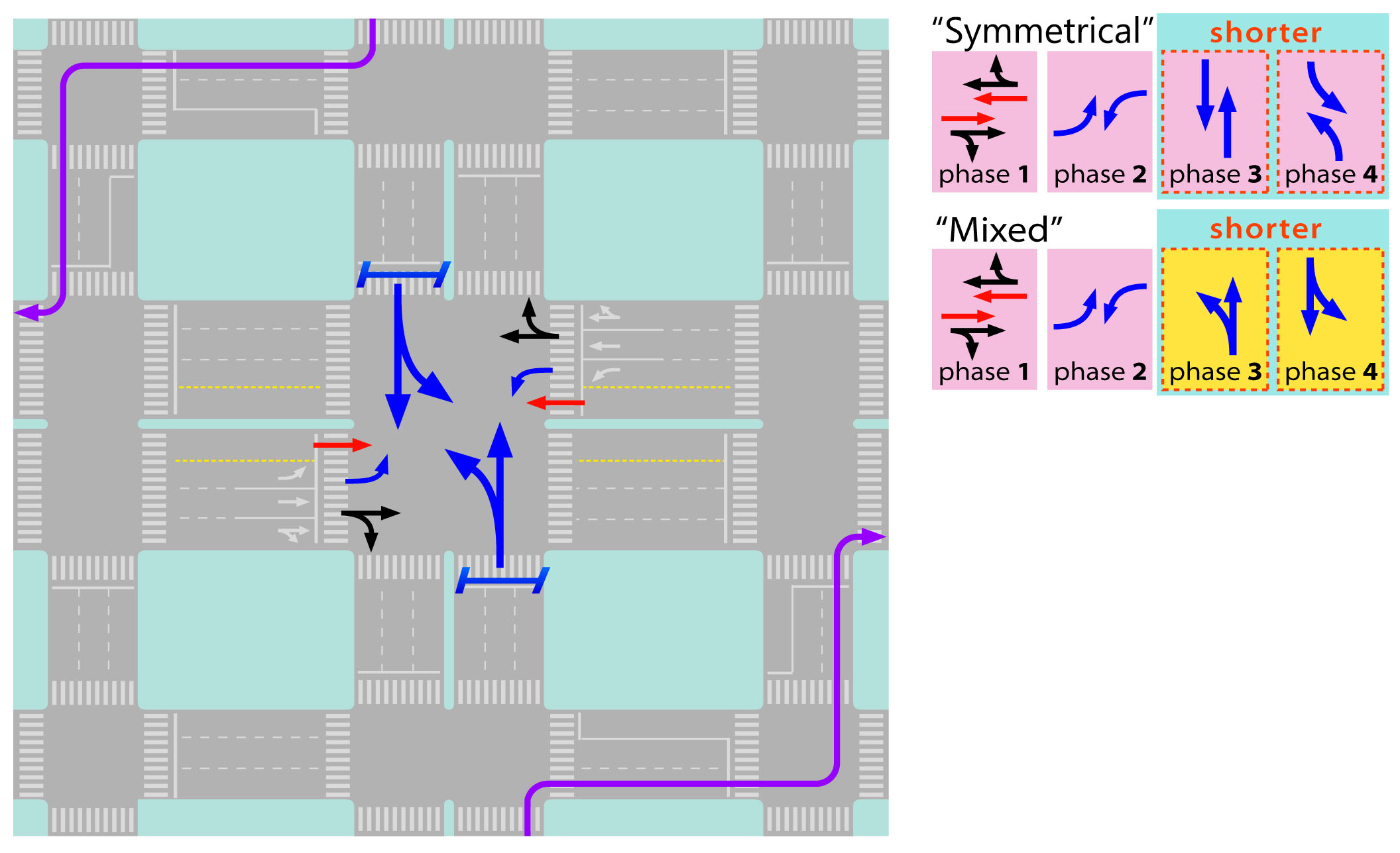
There are several ways of eliminating cross-traffic turns in the main intersection by detouring the flow. These can be applied both to the flows parallel to the corridor and to the flows crossing the corridor (and turning parallel to it). Without cross-traffic turns, the intersection can have only two phases, but applying a detour to only one direction (both ways) means eliminating one phase already.
24.5.2.5Curbside-Turn, Cross-Traffic Turn, and Cross-Traffic Turn (“curb-first”)
This detour follows a curbside detour proposed through auxiliary streets, with a curbside turn at the parallel street before the intersection, followed by two successive cross-traffic-side turns (Figure 24.38). This variation is more effective to apply to the corridor perpendicular to the BRT, as it frees width in its main approach to straight flow only. When compared with other alternatives (discussed below) this detour might be more beneficial to mixed traffic as opposed to the BRT, since it may justify reduction of proportional green time in BRT’s direction.
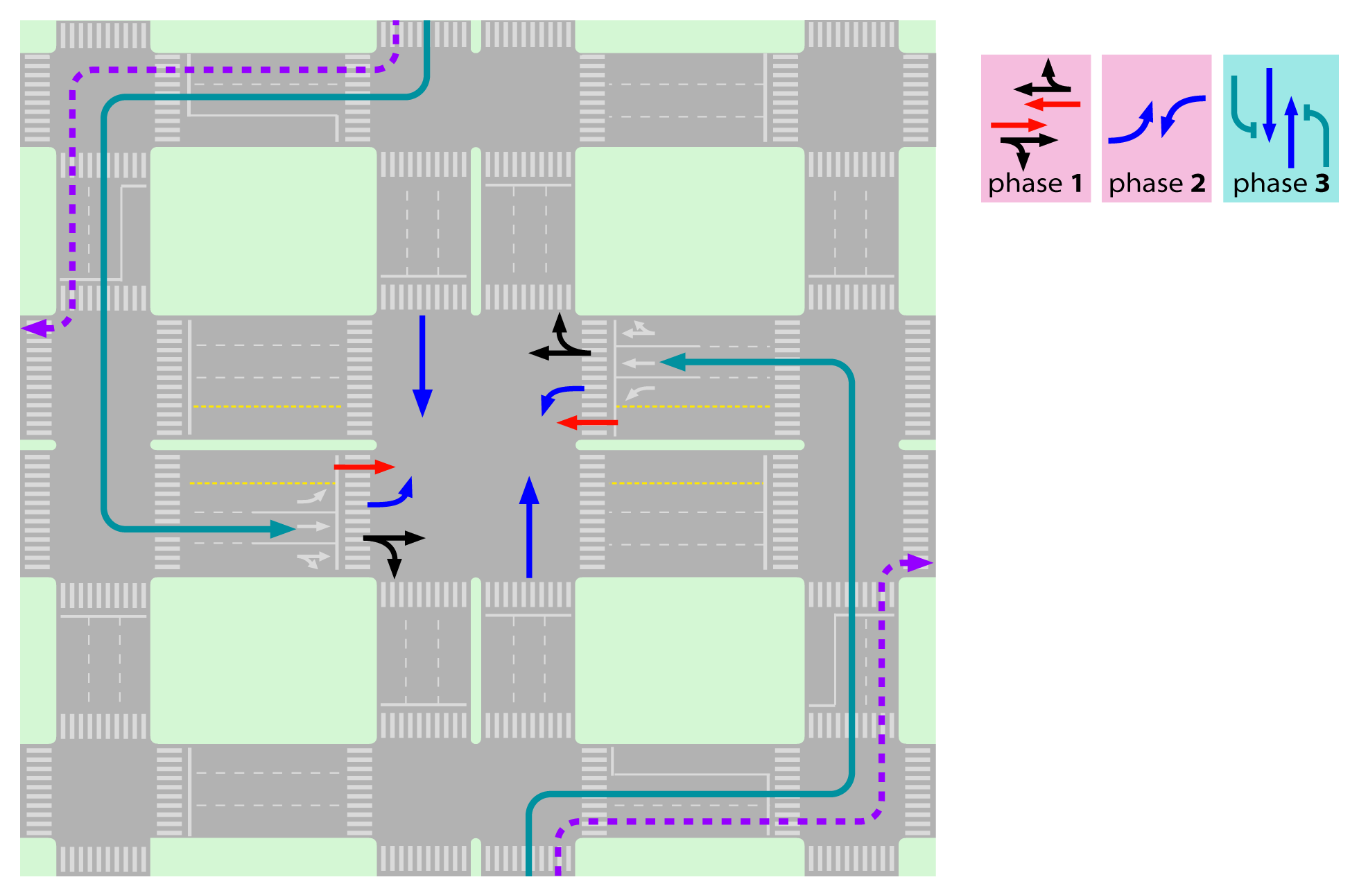
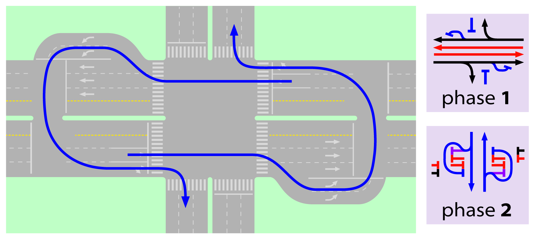
24.5.2.6Loop
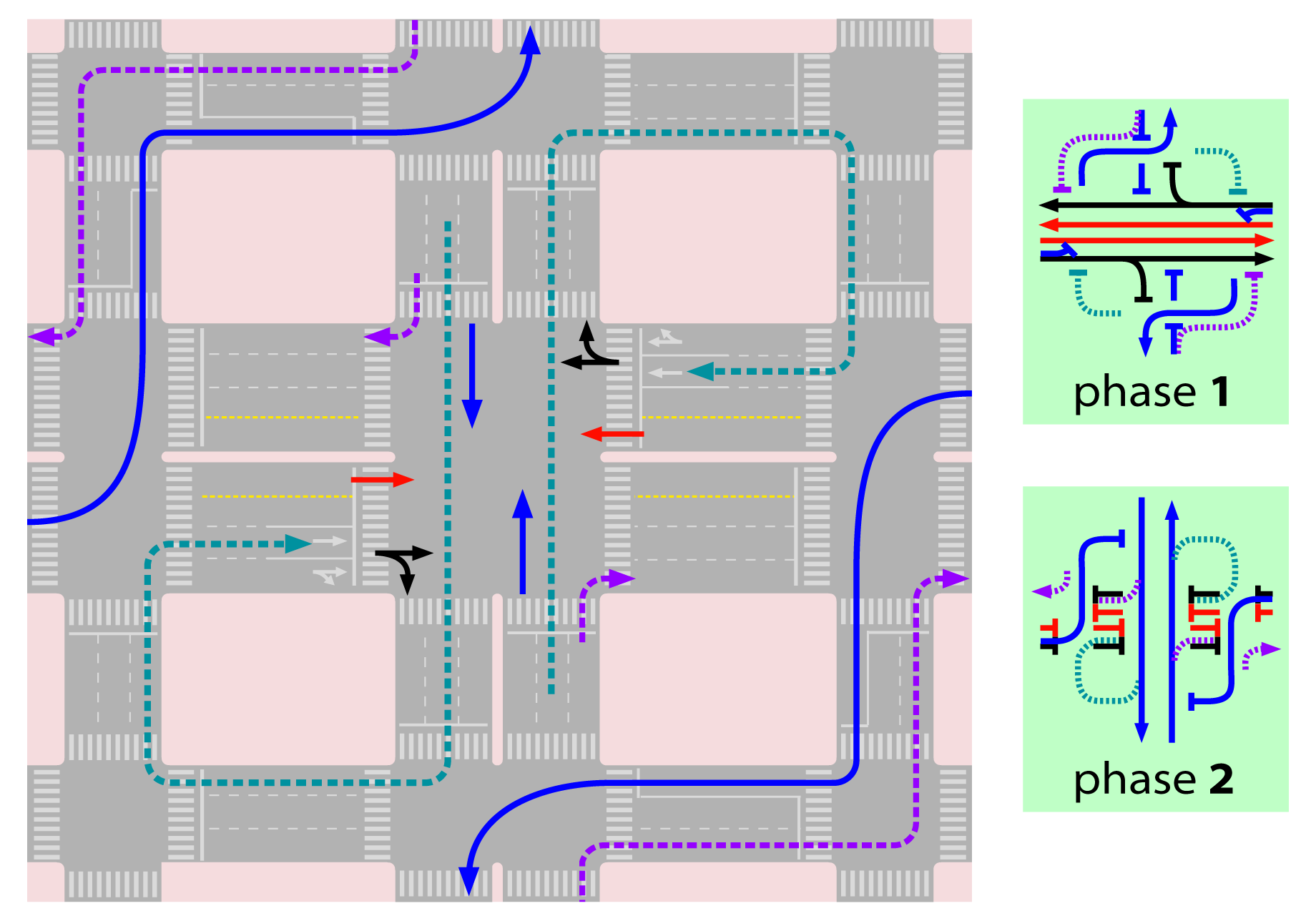
For the loop, the flow looking to perform a cross-traffic turn has to instead cross straight through the intersection and perform three curbside turns and then cross straight through the intersection again (Figure 24.39 shows an application of this flow that is initially parallel to the BRT), even though this has the clear disadvantage of using the intersection twice. Although the other way can be better, this alternative is always interesting for the BRT crossing flow, because it necessarily reduces red times. For the parallel flow it is interesting while flows are low enough not to take one lane width on the crossing-BRT phase.
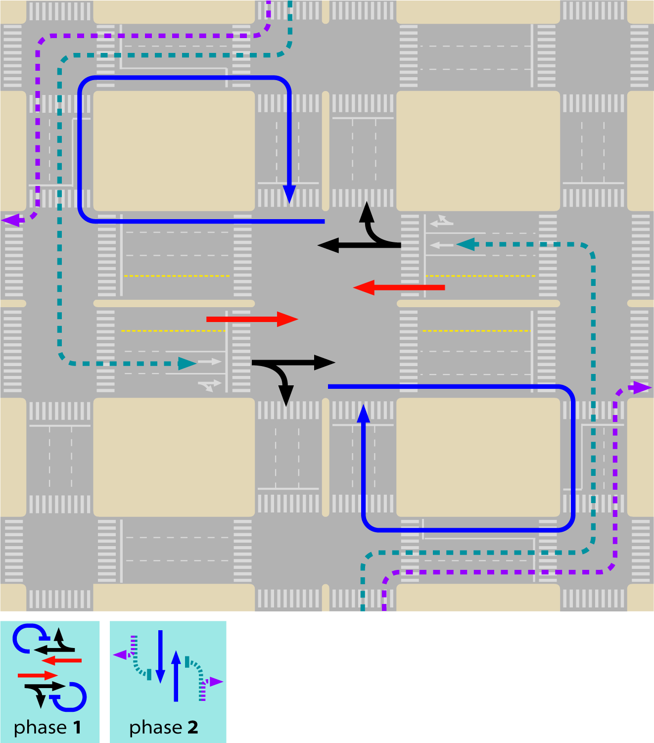
24.5.2.7Previous Cross Turn (“previous cross”)
Before reaching the main intersection, the diverted flow is allowed to cross-traffic turn in a location where there is no perpendicular crossing traffic (i.e., where previously no crossing intersection existed), the opposite straight flow has to be detained to allow this move, but it can be stopped synchronously to the main intersection. After the cross, the diverted flow follows perpendicular to the main corridor until a suitable location for a curbside turn is reached; from there it will run parallel to the original flow in the direction of another intersection in the crossing road, downstream the main intersection, where it will join the flow by means of another cross-traffic flow in a two-stage traffic light (where previously no crossing existed or now has to be forbidden) also synchronized with the main intersection (Figure 24.40).
The “previous cross” detour is the best alternative for the parallel flow to the BRT corridor that wants to turn across traffic on the main intersection because it definitely moves the conflict away from the most crowded intersection. But it cannot be applied in both directions (parallel and perpendicular) as it would require a three-phase intersection for exiting/returning to the main avenues. It also may create capacity conflict if, in the perpendicular direction of approach, the curbside-turn is being diverted, so consideration should be taken to redirect it back to regular curbside turning at the intersection. If cross-traffic turn, also in the perpendicular direction, is diverted by means of the “curbside first,” then serious conflict would rise, so the perpendicular flow shall be redirected to a “loop.”
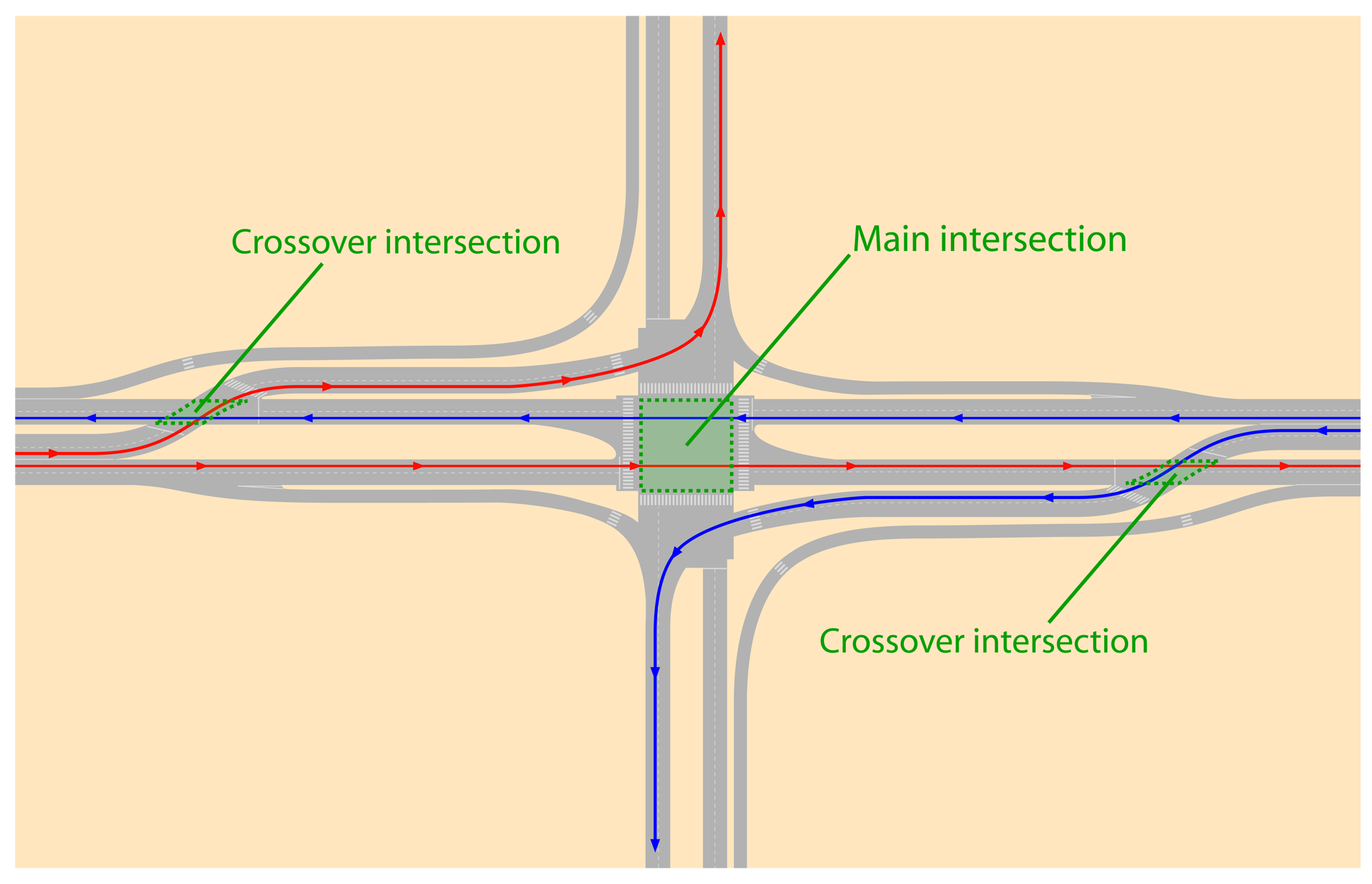
The previous cross alternative is similar in concept to the “displaced left-turn” intersection in the United States (Figure 24.41), which can be applied where width is available.
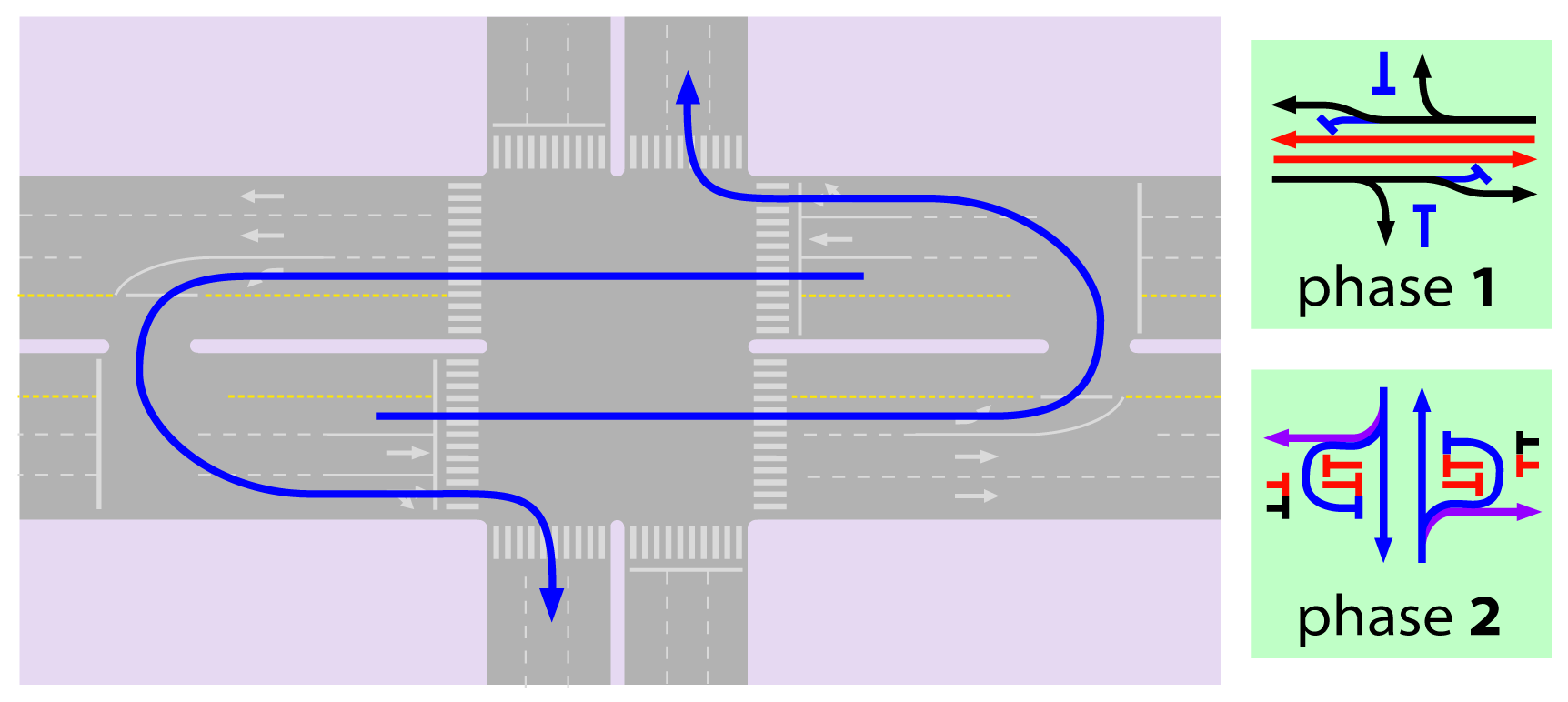
24.5.2.8Curbside Turn and U-Turn (“curb-u”)
A cross-traffic-flow detour is made by first making a curbside turn at the crossing road, followed by a U-turn in the crossing road at a suitable location approximately one hundred meters from the major route, and then driving straight through the intersection. From the main intersection capacity point of view, this alternative has no advantage over the loop as it takes away the same width as the loop in both approaches. It is suitable when the loop is not an option, because the alternative is already congested or too long, which would create political problems with car drivers; besides, there would have to be sufficient width to accommodate the U-turn as well as length for a waiting area. To be applied to the traffic coming from the perpendicular direction to the BRT, as this movement crosses the bus lanes it creates undesirable conflicts for the BRT system. The U-turn traffic light should be two-phase only, synchronized with the main intersection.
24.5.2.9U-Turn and Curbside Turn (“U-curb”)
Another alternative is possible by means of making a U-turn at a median break downstream of the crossing road, followed by a right turn at the crossing road (Figure 24.43).
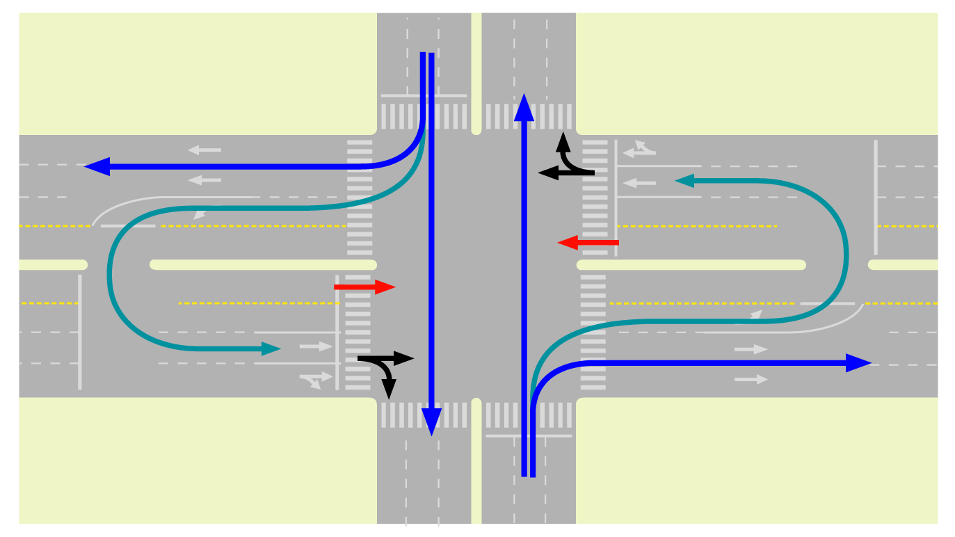
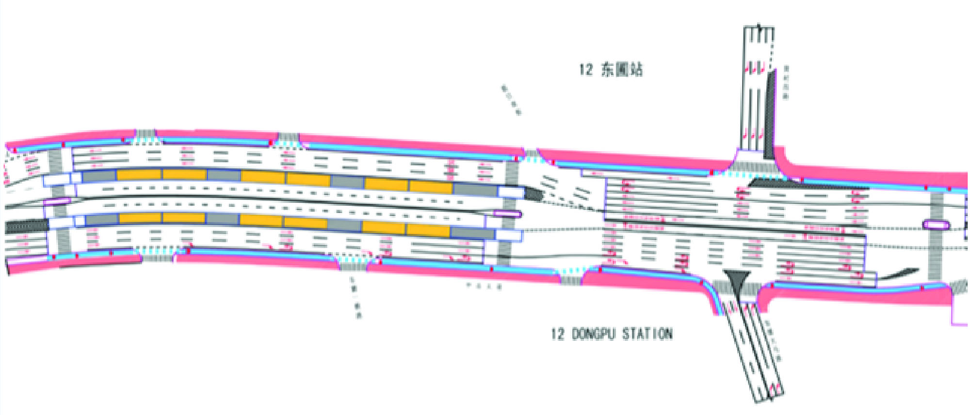
The U-turn and queue area may be accommodated at the curbside instead of in the median side, as shown in Figures 24.44, 24.45, and 24.46, where it accommodates cross-side-turn detoured flows from both the parallel and perpendicular streets: parallel doing U-turn then curbside, the perpendicular doing curbside then U-turn.
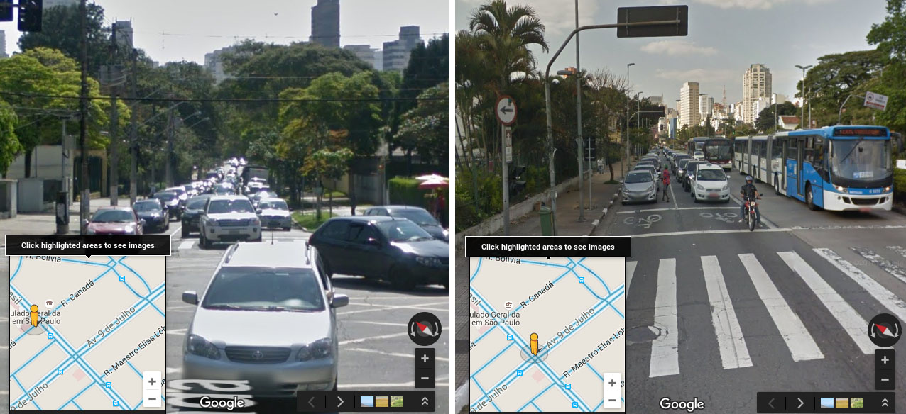
24.5.2.10Diverting Straight Flow: Parallel Street
The use of the immediate parallel street in one way as an auxiliary street is an effective alternative for mixed traffic. Even a narrow two-way street transformed into a one-way street with parking prohibition can be a meaningful alternative for straight traffic and avoid the need for widening and expropriation. If applied both to BRT corridor and the corridor crossing, it can alleviate intersections. In São Paulo it is common that the “auxiliary” streets end up having higher throughput than the main corridors (Figure 24.47).
24.5.2.11Moving Across or Making a U-turn Away from the Intersection
If the station location is seen as imperative, the intersection could be closed in order to avoid problems with the BRT system operation. Mixed traffic can be detoured around it. The examples for curbside and U-turn (Figures 24.48, 24.49, and 24.46) applied this detour to straight movements, too, even if the movements do not always surround the station.
24.5.3Creating Two-Phase Intersections
Many of the detour options assume that an adjacent secondary-street system exists and has the capacity to absorb additional traffic caused by the proposed diversions. When they do not exist, widening one of the roads to accommodate U-turns and/or previous cross-traffic turns is usually a more feasible alternative. Deciding which detour alternatives apply to each flow requires a careful evaluation of both the demand intensity and fluctuations throughout the day in the intersection and surrounding streets, as well as the possibility of widening the approaches.
An infinite number of designs exist, including roundabouts and hamburger-shaped intersections and others that have yet to be created. The goal is to increase the proportion of green time given for the corridor direction, which will result in a natural increase of capacity for traffic.
Alternatives that invert the way—that is, making a right-handed system in a location where a left-hand system is used or vice versa—should not be proposed (in our experience, even if the flow is completely channeled and pedestrians and bicycle crossings are grade-separated, there should be safer alternatives). The common situation of a flowing busway amid congested mixed traffic is enough potential danger to deal with at the intersection. The importance of an enforcement policy to slow down BRT drivers in this situation cannot be stressed enough.
For mixed traffic in particular, measuring travel time alone is not the right metric to evaluate and monitor the quality of a solution. It is very likely (and frustrating) that one will see congestion returning after implementation on a major intersection. When that happens, one must remember that, besides accommodating rapid public transport, there are capacity gains for mixed traffic. Congestion seems to be the only general traffic deterrent, so if a good design will enable more people to cross the intersection by car, then that might mean that either travel times or congestion were eliminated somewhere else or that more people are willing to come to that area and benefit from the activities that part of the city has to offer.
When the adjacent land use is primarily residential, there is likely to be considerable resistance to the above proposals. One should keep in mind that this is a normal pressure of city growth (historically, cities grew out of road intersections), and a broader perspective to regulate the use of land may need to be brought into the project.
24.5.4Comparison Examples
For an initial general analysis of the possible configuration, we graphically present the cycle time as a function of required relative green times for vehicular phases (Figure 24.50). We consider both the situation where a pedestrian phase is required and not. When required, we assume the pedestrian phase will need 10 seconds plus 4 seconds of clearance, which is the time needed for crossing three lanes. The clearance (or lost time) for each phase is 4 seconds as well.
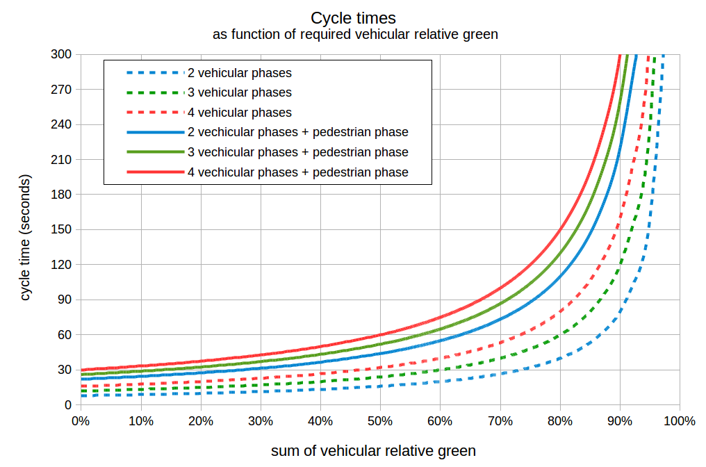
By observing the chart, it is clear that when the pedestrian crossing phase is present, at the moment green times are required to be 75 percent, the intersection is near to collapse. This threshold is between 80 and 85 percent if no pedestrian phase is required.
The chart also shows that increasing cycles beyond 120 seconds is not efficient in any situation. In the best case (4 vehicular phases plus pedestrian phase), increasing it to 150 seconds (+25 percent) results in a 5 percent increase in capacity, and raising it to 300 seconds will add 10 percent more capacity. Such a desperate measure will of course prevent queueing formation during the peak hour and that certainly reduces travel times, but other measures can be much more efficient.
If the BRT users are not to be stuck in traffic, and delay is computed equally to the car users, then it is very likely that raising cycle times above 120 seconds will result in overall time losses. Furthermore, if curbside turns are detoured or refuge islands are used as discussed in Section 24.9, then a proper set of two-phase signals will not require a pedestrian-only phase. In such a situation cycle times above 60 seconds are likely to be useless, and cycle times above 90 seconds are certainly not justifiable. As seen in Section 24.3, short cycles greatly reduce the chances of spillbacks on the busway, hindering stations.
For a comparison of different configuration impacts, we will assume a very symmetrical four-leg intersection, where the flow from each origin is equal and the left and right turns each represent 25 percent of traffic movements, straight represents 50 percent, and there is no U-turn demand. We will also assume a three-lane approach for mixed traffic in each leg as previous figures in this section show, with saturation capacity flow rate of 1,800 pcu/hour. When required, only one lane is used for cross-traffic turns per approach. We maintain the same assumptions to draw the chart regarding clearance times (4 seconds per phase change) and pedestrian phases (14 seconds per phase when phase required, and we assume it is not required in two-phase intersections).
24.5.4.1Typical Four-Phase Intersection
For comparing the four-phase intersection, we will fix cycle times at 120 seconds (2 minutes) and evaluate the effect of green time for the straight flow in one of the directions considering detouring curbside turns for each direction (two ways), and we will divide the overall capacity of the intersection by the number of lanes approaching it (NLanes in our example is 12 and results are in table 24.3).
Table 24.3Four-Phase Capacity Examples
| Cycle Time (seconds) | Phases | Direction 1 Curb-Side-Turn | Direction 2 Curb-Side-Turn | Direction 1 Straight Movement Green Time (seconds) | Average Lane Capacity (pcu/hour) |
|---|---|---|---|---|---|
| 120 | standard | - | 23 | 338 | |
| 120 | symmetrical | - | - | 31 | 416 |
| 120 | standard | detour | - | 19 | 338 |
| 120 | symmetrical | detour | - | 23 | 404 |
| 120 | standard | - | detour | 26 | 338 |
| 120 | symmetrical | - | detour | 35 | 404 |
| 120 | standard | detour | detour | 23 | 338 |
| 120 | symmetrical | detour | detour | 26 | 390 |
Under the proposed scenario, a “standard-four-phase” signal has 90 seconds to distribute among the phases (30 out of 120 seconds are for pedestrian plus clearance times of phases changes), so this means 22.5 seconds per phase (rounded to 23 in the table) in the symmetrical situations. By detouring curbside turns to one side only (letting only 75 percent of demand be served), 3 seconds can be removed from the lesser demanded phases and passed to the other two (19 and 26 seconds); the capacity of each lane of each approach is always equal, meaning that 4,050 vehicles overall could pass through the intersection in one hour in the 12 lanes (= 338 x 12).
In comparison, the “symmetrical phases,” which do not require a pedestrian phase, can distribute 104 seconds among the phases, and it ends up being 31 seconds for the straight traffic and 21 seconds for the cross-traffic turn (this last information is not on the table but is deductible). If lanes could be used in fractions, then allocating three-quarters of a lane to cross-traffic turns would lead to a balanced situation of 26 seconds of green time for each phase, which is the case when both curbside turns are removed from the intersection.
On the balanced situation, when the symmetrical phases have the lowest capacity, they still have the same capacity as the standard phases, the higher throughput being a consequence only of the absence of the pedestrian-only phase. As a general rule, symmetrical phases are more efficient than standard phases. Mixed-phase results are not shown, but they are in between, closer to standard phases as they require pedestrian phases, too.
24.5.4.2Reducing Number of Phases Effects
The previous discussion about four-phase intersections lay the groundwork for not considering the “mixed-four-phase” alternative in the following examples. This is also a reason why there is no need to present a previous cross-traffic turn, interlacing the BRT lane and mixed traffic (Figure 24.82), which shifts mixed traffic to the median side into a position that allows a standard four-phase intersection to work where no other alternative is possible; the symmetrical-phases signal works better.
To compare the effects of alternative schemes for phase reduction, we will consider a 90-second cycle time without a pedestrian-only phase but with an additional BRT lane in one direction on the median side (also as shown on most figures in this section). The resulting green time for the BRT for each alternative is presented beside the intersection capacity of mixed traffic in Table 24.4, where:
- Average lane capacity: the average of the mixed-traffic lanes capacity that would be measured at the stop lines approaching the main intersection;
- Overall intersection capacity per lane: in certain configurations, some vehicles pass through two stop lines in order to execute their turning movements, and this measure would be similar to average lane capacity above, except that it does not count the second passage of the same vehicle.
- Total throughput with auxiliary intersections per lane at intersection: this adds the flows that were completely diverted away from the main intersection (curbside-turn detour and previous cross-traffic-turn detour) as if they were effectively passing through the intersection. By bringing the value to the number of lanes of the intersection, this presents a practical estimate of how much the capacity of the main intersection can be pushed to benefit from using the auxiliary ones.
Table 24.4Increasing Capacity Examples
| Option | Cycle Time (seconds) | Phases | BRT Direction Curb-Side-Turn Detour | BRT Direction Cross-Traffic-Turn Detour | Perpendicular Direction Curb-Side-Turn Detour | Perpendicular Direction Cross-Traffic-Turn Detour | Figure | BRT Green Time (seconds) | Average Lane Capacity (pcu/hour) | Overall Intersection Capacity per Lane (pcu/lane) | Total Throughput with Auxiliary Intersections per Lane at Intersection |
|---|---|---|---|---|---|---|---|---|---|---|---|
| A | 90 | symmetrical | - | - | - | - | Fig. 24.35 | 22 | 395 | 395 | 395 |
| B | 90 | symmetrical | detour | - | - | - | 16 | 384 | 384 | 439 | |
| C | 90 | symmetrical | - | - | detour | - | Fig 24.37 | 25 | 384 | 384 | 439 |
| D | 90 | symmetrical | detour | - | detour | - | 19 | 370 | 370 | 493 | |
| E | 90 | 3 | - | - | detour | curb-first | Fig 24.38 | 43 | 496 | 496 | 567 |
| F | 90 | 2 | - | loop | detour | curb-first | Fig. 24.39 | 51 | 819 | 716 | 819 |
| G | 90 | 2 | - | Previous-turn | detour | loop | Fig. 24.40 | 47 | 819 | 702 | 936 |
| H | 90 | 2 | - | Previous-turn | - | loop | 41 | 819 | 716 | 819 | |
| I | 90 | 2 | detour | curb-first | detour | curb-first | 41 | 819 | 819 | 1092 | |
| J | 90 | 2 | - | loop | - | loop | 41 | 819 | 655 | 655 | |
| K | 90 | 2 | detour | loop | detour | loop | “clove like” | 41 | 819 | 614 | 819 |
| L | 90 | 2 | - | u-curb | - | curb-u | Figs. 24.43 and 24.44 | 49 | 819 | 655 | 655 |
| M | 90 | 2 | - | curb-u | - | u-curb | 33 | 819 | 655 | 655 |
In our scenario, detouring all curbside turns away implies that 25 percent of cars are not using the approaching lanes to the intersection, and 75 percent of them are. So for each vehicle at the intersection, there is an additional third outside, which means a 33 percent increase in “intersection capacity.”
In comparison with the four-phase (symmetrical) signal, even the three-phase signal implies a considerable increase of green time for the BRT. Reducing 4 phases to 3 leads to a 25 percent increase for the capacity at the intersection (and 50 percent considering auxiliary intersections) with satisfactory relative green time near 50 percent. Meanwhile, from the point of view of mixed traffic throughput, the reduction from 4 to 2 phases in the worst cases (U-turn alternatives and only loops: J, L, and M), an 80 percent increase for the throughput occurs at the intersection, and in the best alternative (option I), there is a 107 percent increase at the intersection while green times are in the same range (except for alternative M, which uses U-turns at the perpendicular street). Implementing a two-phase signal is clearly the best thing to do.
When traffic signals are balanced to serve the demand with a two-phase traffic signal, it will result in the capacity of about 820 pcu/hour. For this situation a cycle of 90 seconds with 4 seconds of clearance is typically used. Additionally, if the flow looking to turn is placed on the (curbside) parallel streets in both directions (option I), then one can reach an equivalent of 1,092 pcu/hour. This results in 60 percent of uninterrupted lane capacity as an average for two directions, which is likely to represent 75 percent of the average of the best grade-separated solution and be better than many graded-separated solutions (see Section: 24.10.3 Restricting Turning Movements Together with Grade Separation). Plus, this is 320 percent of the average capacity of a standard four-phase intersection. Clearly, the consideration of the detour alternatives to reduce signal phases can do a lot to increase green time for the corridor as well as capacity for mixed traffic.