28.1Physical Integration
Art has to move you and design does not, unless it’s a good design for a bus.David Hockney, English artist associated with the ‘pop art’ movement, 1749 – 1827
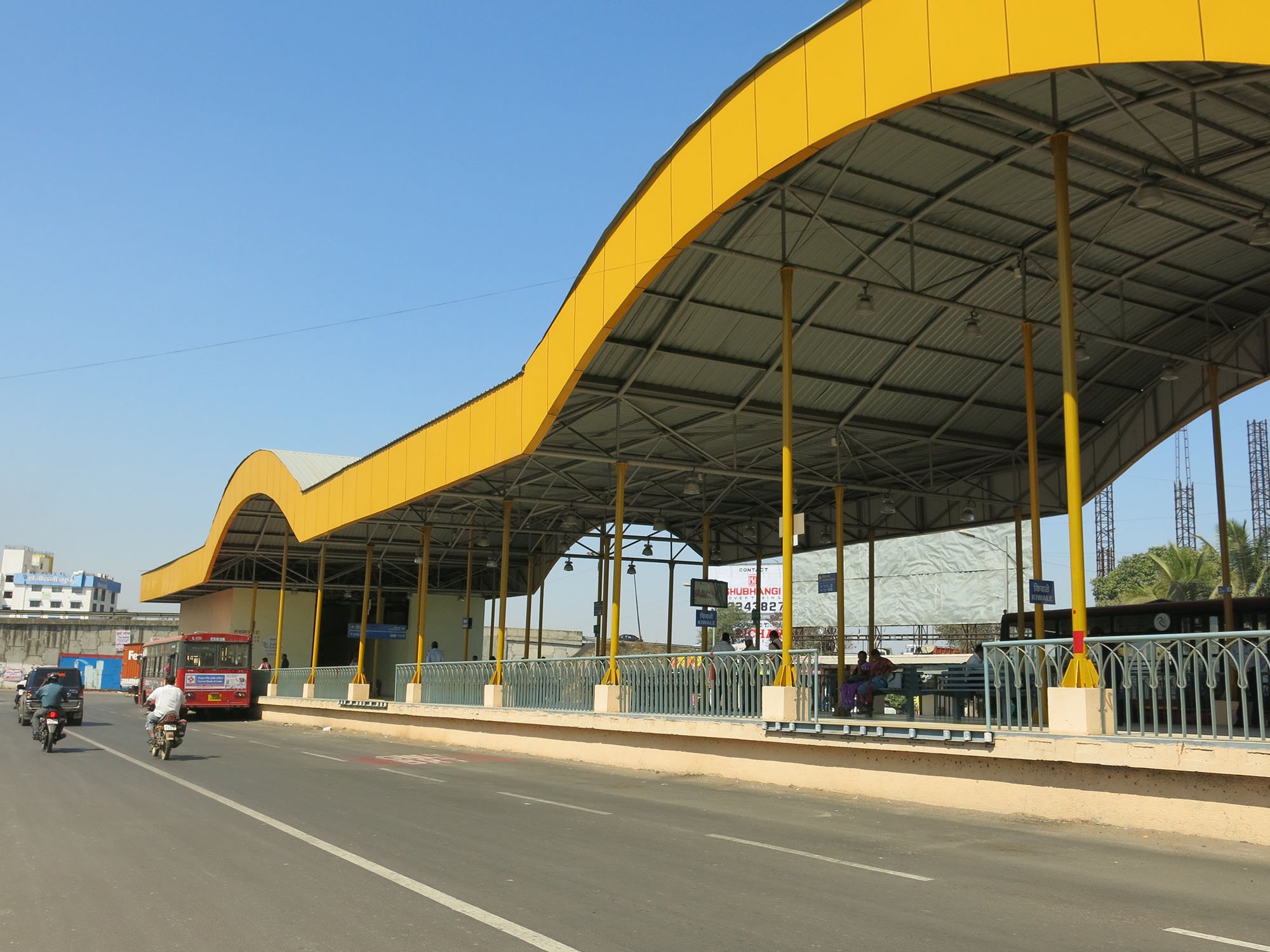
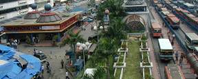
Physical (or spatial) integration describes efforts to co-locate the various parts of a transport system. This generally occurs at stations, but also happens elsewhere in the network. Examples include taxi stands outside bus terminals, walkways connecting stations directly to adjacent buildings, stations serving various bus and train lines, and bikeways along BRT routes, among others.
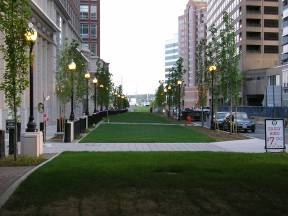
The first priorities for physical integration within a BRT network, essentially pre-requisites of good system design, is with the pedestrian and cycling environment surrounding the station, terminal or multimodal facility (see Chapters 29: Pedestrian Access and 31: Bicycle and Pedicab Integration for more information) and with the different lines and services of the BRT system itself by creating an easy transfer between them.
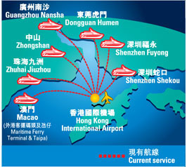
BRT can be complementary with other urban and long-distance public transport options. Cities with existing metros and urban rail services should ideally integrate these options with BRT. Cities with water transport systems should also seek to closely integrate these systems with the BRT network.
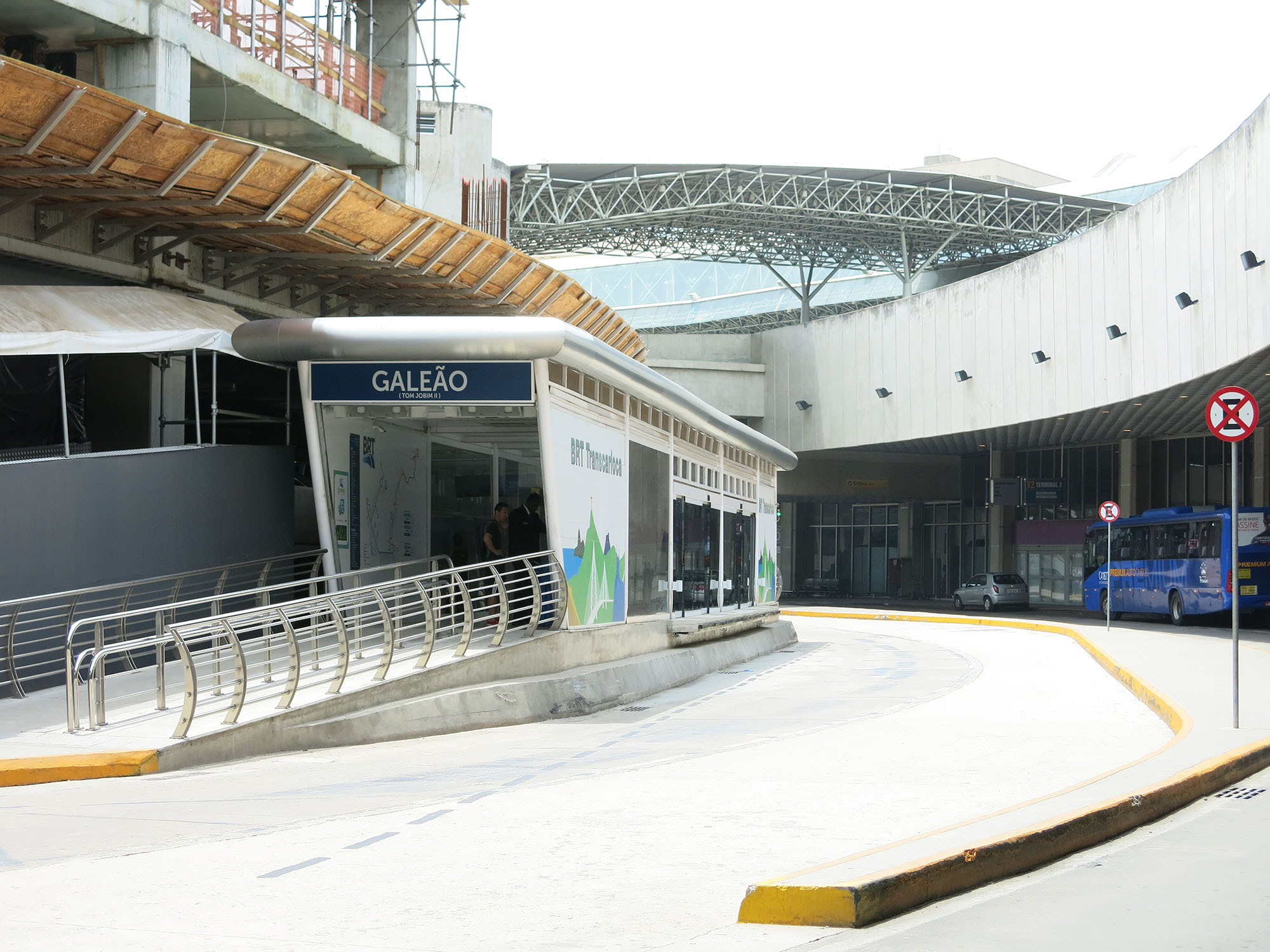
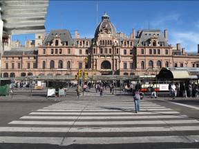
BRT can be integrated with long-distance public transport infrastructure such as long-distance bus stations and train stations, and, in some cases, airports. Again, physical planning is key to making this option viable. Customers from such modes often are carrying luggage or goods and need a convenient transfer mechanism.
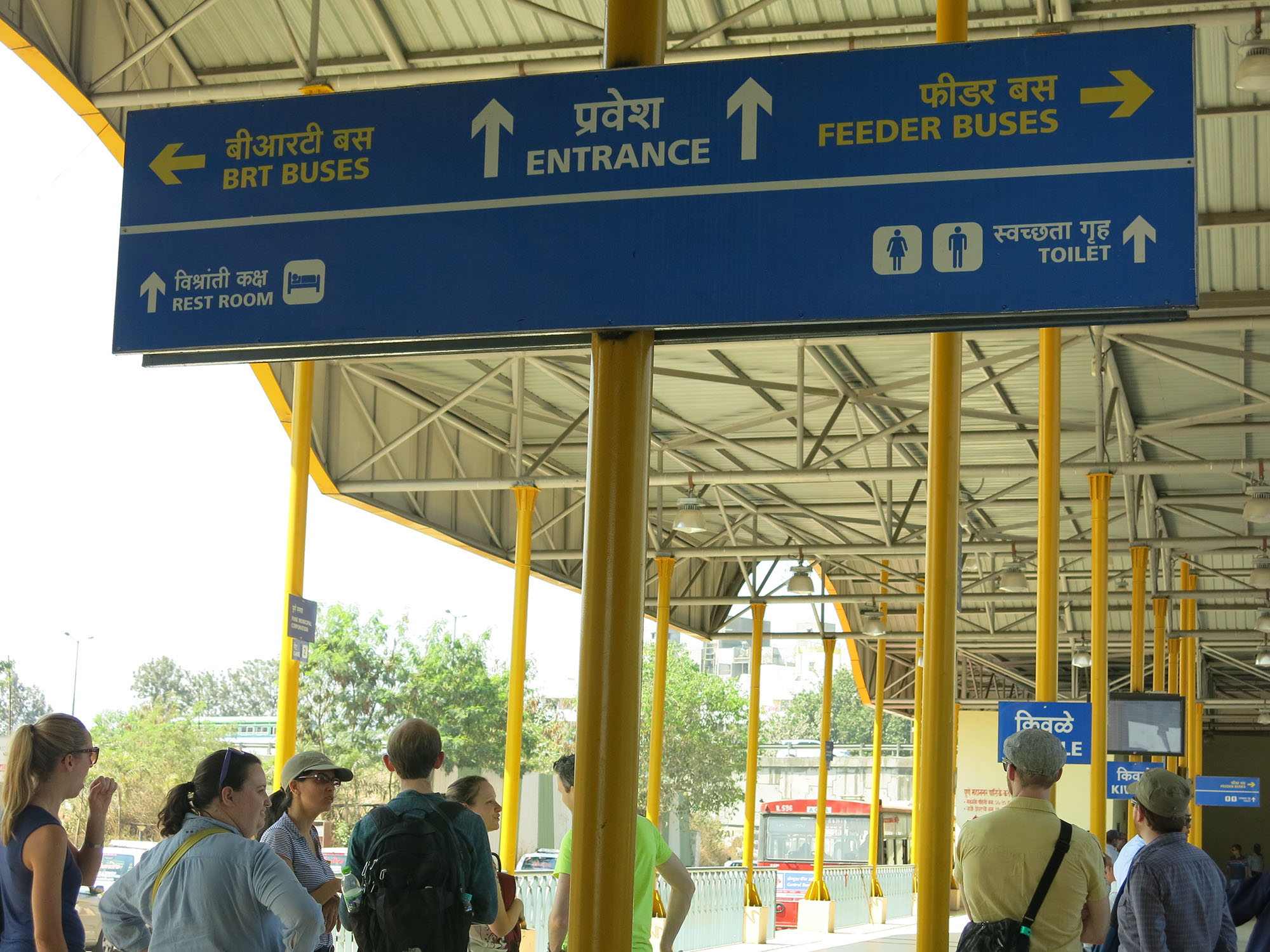
Aside from BRT buses and feeder buses, which form an integral part of the BRT system, other local bus services may interface with BRT stations. These include municipal buses, private buses, and various coach and bus shuttle services, such as employee buses, hotel coaches, and even school buses. A high-quality walking network is desired for access to buses not integrated into the BRT system or otherwise located in an intermodal terminal shared by both BRT and local buses.
28.1.1Networks
At the planning level, circulation networks (including transport networks) should be organized to share resources and maximize coverage. The public right-of-way is historically where roads and services are located, including BRT. Not coincidentally, many corridors contain facilities for many modes: streets, bikeways, busways, and utilities. Organizing the BRT network in concert with other networks allows maximum integration. Other modes and networks that BRT can connect with include:
- Airport;
- Bike (bikeway, public bikes);
- Bus (city, school, jitney);
- Coach (long distance, inter-city, charter);
- Ferry (seaport);
- Light Rail (tram, streetcar);
- Metro (skytrain, elevated);
- Train (inter-city, suburban);
- Walking (footpaths, connections to buildings, crosswalks, bridges).
This could include high quality walkways and crosswalks around the BRT corridor, parallel bike lanes along the corridor, BRT intersecting with a rail corridor, or BRT leading directly to and integrated with airports, seaports, and other terminals.
The different opportunity for customers to transfer is influenced by the physical relationship of one mode to another. Examples include BRT platforms adjacent to rail platforms or BRT platforms directly linked to intercity coach departure points. BRT stations can be planned and designed as the primary interface of customers from one mode to another. Public transport planners can, during the planning phase, optimize the location of BRT roadway alignments to interface other existing modes. Platforms can intersect at predetermined levels linking ‘paid’ customers and maximizing connectivity. Practical and technically constructible linkages of BRT infrastructure with other modes can help support a ‘network effect’ within public transport systems. The network effect can be described as multiple points created for the opportunity to transfer between many different services of one mode with the different services of another mode. Customers can plan trips based on their opportunity to transfer between services at key points.
Political realities factor in deciding what to integrate. Generally it is easier and more convenient for BRT to integrate with other modes also managed by the agency or jurisdiction that manages the BRT. For example, if both BRT and bicycles are part of the transportation agency or if BRT, taxis, and Metro are part of the public transport agency, it is much easier to integrate the services and spaces. If the rail service is owned by a completely different agency from the BRT system, integration becomes harder to achieve. When two modes are controlled by different operators, there is little motivation to make the connection as smooth as possible. These realities hone the focus of integration.
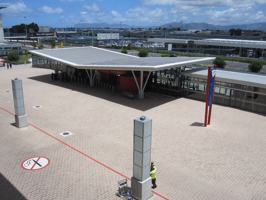
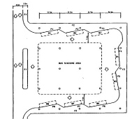
28.1.2Terminals and Stations
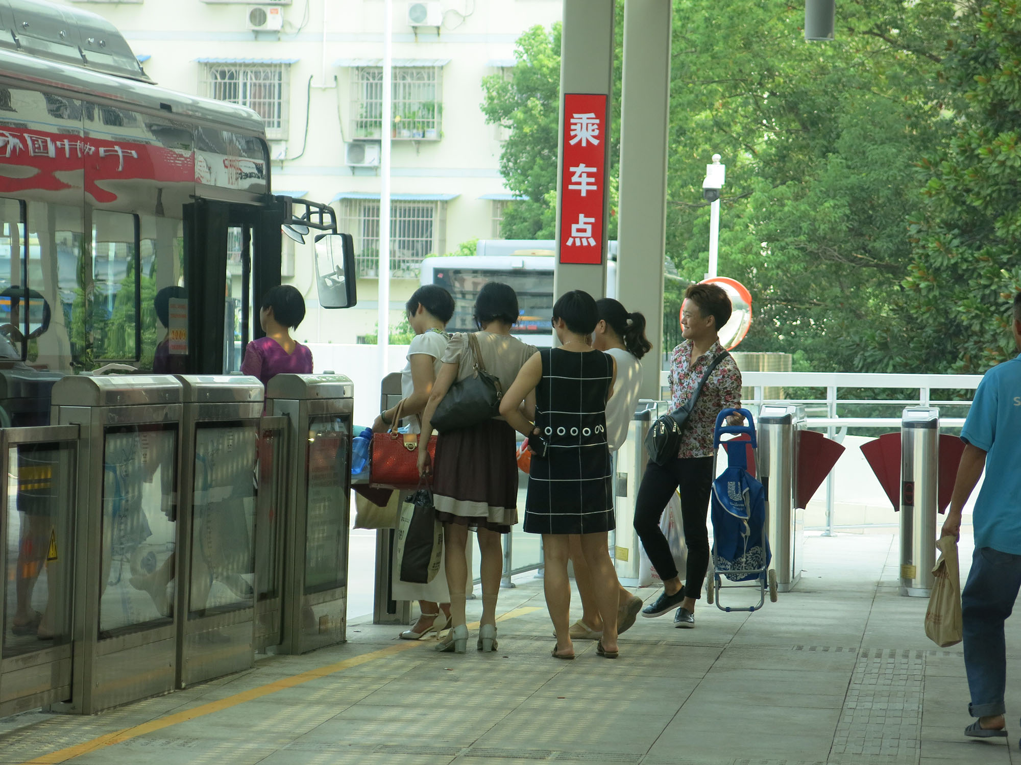
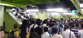
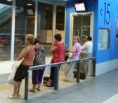
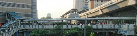
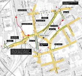
The physical planning of terminals and stations is a crucial part of successful public transportation network integration. Small-scale intermodal transfers often happen in an ad-hoc manner: a person may lock a bicycle to a lamppost and enter a BRT station; hail a taxi on the street after coming out of a BRT station; or walk from a ferry pier to the nearest BRT station. Even such “spontaneous” inter-modality requires some degree of physical facilitation, such as a continuous pedestrian realm, abundant bicycle racks, and easy curbside access to taxis. However, systemic intermodal transfers, which are meant to handle large numbers of customers and accommodate peak commuting patterns, require the careful planning of intermodal transfer facilities in order to ensure they can cope with high flows of people. The challenge of multimodal integration is a physical challenge often trying to connect modes that are offset both horizontally and vertically.
Three concepts undergird the planning of intermodal transport facilities:
- Forecasts. Forecast all expected transport modes, with details on the mode splits and expected intermodal transfer flows. In the absence of reliable forecasts, plan for worst-case yet plausible scenarios.
- Flexibility. Anticipate changes in the market, operators, vehicle types, and modes. Planning assumptions should be reviewed periodically and the terminal design adjusted as much as possible.
- Expandability. Design for long-term forecasts and for the facility to be expanded to accommodate that growth. Concept plans for the expansion should be in place at the time of the initial design.
Forecasting underpins any successful design of transport facilities. In less mature cities, where there is still a lot of growth, forecasting becomes harder. When the data does not exist, the next thing is to maximize what can be done on the site. If possible, plan for greater demand than anticipated as a way to safeguard against poor data. Another way to safeguard is to use a modular design, so that expansion can happen if needed.
In the absence of forecasts, one method to figure out how to size various facilities, such as platforms, ticketing areas and corridors, is to design around capacity and plan for the plausible worst case scenario, which in the case of transit systems is when everyone gets on and off. That scenario usually only happens at a terminals. Walkways, platforms, stairs / escalators all need to be balanced to cater to that maximum capacity.
When designing these facilities, the following principles instruct that process:
- People get priority. As much as possible, the first priority is to design for the people using the facility and the services, and not design around the different transport modes.
- To integrate different modes in order to streamline and optimize the overall transport network functionality. Without transport hubs, there is a tendency to have less coverage and significant route overlaps, all of which makes for a less efficient system.
- To provide a seamless transfer. Given the choice, most people would prefer a non-stop journey, whether from door to door (by foot, bike, or private vehicles) or on a single mass transit mode. High customer level of service (LOS) is therefore key to nudging commuters to use public transport on journeys requiring intermodal transfer. This includes short walking distances, few and assisted level changes, and comfortable transfer environment, including weather protection where appropriate.
- To maximize commercial opportunity within the hub in order to provide additional revenue source to subsidize the hub maintenance and operation. The high traffic flow is attractive to many types of commercial operators and can generate income without compromising operations or LOS.
- To integrate within the urban environment in order to maximize the pedestrian catchment area, encourage transport-oriented development, and maintain the continuity of the surrounding urban fabric.
- To separate motorized and non-motorized modes. It is advisable to locate motorized modes (bus, taxis, car parking, para-transport, coach) to one side of a terminal and non-motorized modes (walking, cycling, pedicabs) to another. It is best for motorized facilities to be located for easy access to highways and the non-motorized modes directly adjacent to built-up areas. This, however, should be done without leading to a “hostile” interface with the urban environment.
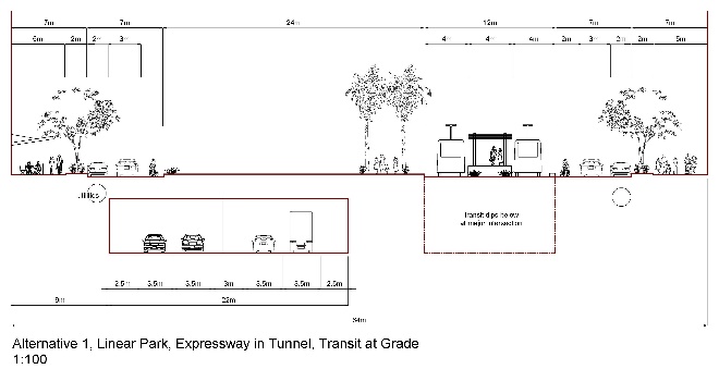
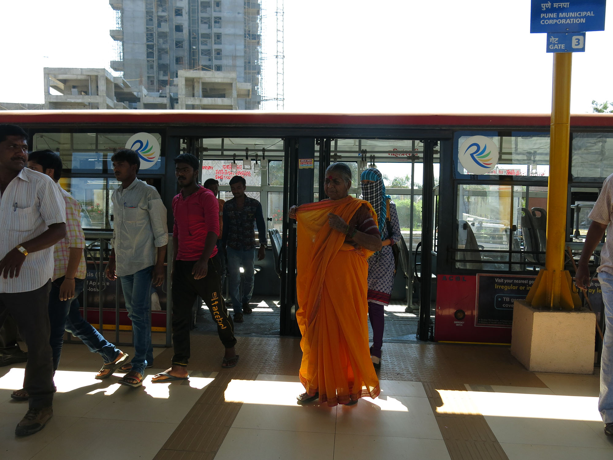
As BRT stations are often located at street level in the median, connecting to any other mode will typically require crossing the street or going up or down a level.
Urban Design and Land Use
The design of the station should include high-density, mixed-use development to maximize the benefits and synergies between the transport accessibility and land use. It should be as organically integrated in the surrounding area as possible, in terms of use, mass, and accessibility. Transport hub “fortresses” surrounded by high-capacity roads create a rupture in the urban fabric.
Building Organization and Layout
The following apply for all types of transport terminals, from bus stops to airport terminals.
- Provide sufficient LOS. Every element in a transport facility needs to be designed and sized to meet the target LOS. Areas with insufficient space will be perceived as bottlenecks and excessive space will be seen as a costly overbuild;
- Size for Peak Conditions. The forecast peak flow of customers forms the basis for sizing all terminal elements, including platforms, corridors, waiting areas, ticketing, queue space, and escalators. There are different methods of determining the peak conditions for the purpose of design (which is usually not the same as the “worst case” peak), and different parts of the terminal may require different methods. The flow analysis must be detailed enough to provide sizing guidance for each and every terminal element; important to sizing considerations are queueing areas, such as at the top or the base of stairs, turnstiles, etc.
- Take advantage of non-overlapping peaks. Most urban transport terminals witness two daily peak travel periods (morning and evening) which typically feature opposite flows. Good design takes advantage of this phenomenon to minimize construction costs by placing elements such as escalators, stairs and turnstiles so that they can serve flows going in either direction. This may require a dynamic assignment of escalator directions, turnstile orientation, railings, signage and other elements by the terminal operational staff;
- Minimize conflicting flows.
- Cross flows create conflicts, thereby reducing capacity and creating confusion and discomfort. They should be avoided as much as possible;
- Counter-flows within the same corridor can also slow traffic unless clearly separated. In larger terminals with significant surges and distinct movement patterns, such as airports and long-distance rail stations, separation of arriving and departing customers may be advisable;
- Minimize walking distances from the station entrances to the boarding area and for intermodal transfer. Transfer distance requiring more than a five minute walk is a deterrent for many customers; keep distances short and direct;
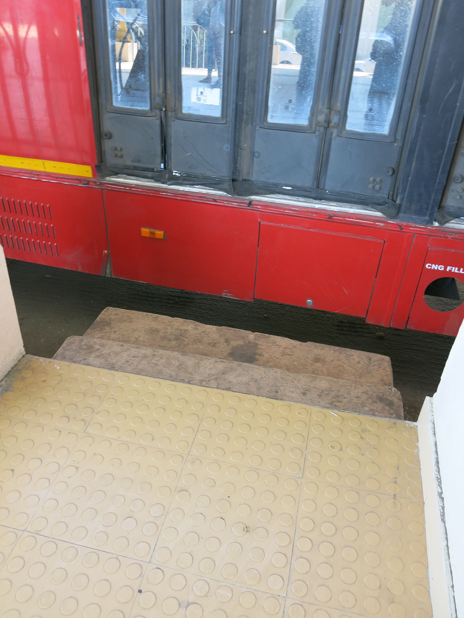
- Minimize level changes. Level changes are uncomfortable for customers, increase journey time, and vertical circulation elements such as escalators and elevators are costly to install and maintain; as much as possible, make vehicles change levels, not people. However, if level changes are a must, make them as easy as possible by the use of gentle ramps, escalators, and elevators, with mechanized modes strongly recommended for upward movement;
- Vertical circulation. Escalators, elevators and inclined travelators should be designed carefully to provide the target LOS with sufficient redundancy. For example, a facility should have two elevators for redundancy considerations, even if demand only requires one. In long-distance terminals special consideration should be given to luggage portage;
- Avoid road crossing. This is in particular relevant for bus and taxi bay access, although pedestrian bridges and underpasses should be seen as a solution of last resort as they inconvenience passengers. Terminal planning should attempt to create contiguous pedestrian-only zones on a single level;
- Easy wayfinding. No amount of online information makes up for good, intuitive wayfinding in the terminal itself, comprising of signs, station maps, and directories listing the transport services provided. Planning the station with simple intermodal transfer routes and open sightlines greatly helps. This is particularly important in intermodal hubs serving non-regular users, such as tourists and crowds going to event venues.
One way to judge the success of the building design is by the Level of Service (LOS). The classic metric of LOS is related to capacity and defined in terms of space per person for queueing areas, space per person per width per minute in flow areas, and the number and width of stairs and escalators. Other ways to evaluate LOS could be the number of level changes in a journey (the lower the better), minimizing cross-flows, no bottlenecks, etc.
One of the key sizing principles in transport facilities is ensuring that the platform can be cleared by the time the next vehicle arrives. In the case of buses, the designer will need to know how many people are disembarking the bus, the frequency of the bus, the number of bus bays and where the customers are going. For example, if a 12-meter bus comes every minute to each of the two bus bays, and 50 passengers disembark from each bus, 100 people will need to clear the platform every minute before the next set of buses come through. What happens if they haven’t cleared the platform yet when the next two buses come in, for example because they have to negotiate a narrow stairwell or an exit with only two turnstiles? The balanced sizing of all station elements against such “worst case scenarios”, including some redundancy provisions, will ensure such situations are avoided.
Box 28.1 Technical Operating Envelops
A specific study comparing the ‘technical operating envelops,’ or the design parameters and space needed for different modes and vehicles, of one vehicle to another within the BRT network and between vehicles of different modes is useful to determine the compatibility and consistency of customers accessing vehicles. This is particularly important that platform-boarding heights are consistent along their length for the co-location of vehicles using platforms and so the ease of passenger accessing different vehicles is optimized. Differential boarding heights can be provided along a platform should the vehicles be significantly different from one to the other. The ‘tracking’ of vehicles for pulling in and out of platforms, the turning circles including sightlines of vehicles and the location of doors that provide a consistent boarding and alighting location on platforms will assist in the assessment of vehicle to vehicle integration. Consistent standards for the protection of customers from vehicles and from the different power sources those vehicles use should also be examined. Invariably the differences in the operating envelops of vehicles will determine the physical proximity of one vehicle to another defining the minimum distance customers have to negotiate between modes.
Building Design and Facilities
Chapter 25 covers the building design of the stations and terminals. Here is a summary of main concerns for multimodal facilities:
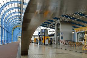
- High quality design is recognized and respected. Many transport terminals (New York’s Grand Central Terminal, Mumbai’s Chatrapati Shivaji Terminus - a UNESCO Heritage Site, Moscow Metro Stations, Paris Metro Stations) have become beloved civic structures over the centuries;
- Cleanliness. It is important to design terminals so they are easy to clean and maintain. Surveys reveal that customers rank cleanliness at the top of their concerns regarding transport facilities;
- Weather protection is one of the most important features of a successful transportation terminal, especially in cities with a harsh climate. The ideal terminal will extend the same weather protection offered on the vehicles themselves, including air conditioning, and avoid any “weak links” such as open-air passages;
- Air quality must be high with a high degree of fresh air replacement, especially in bus terminals and deep subway tunnels;
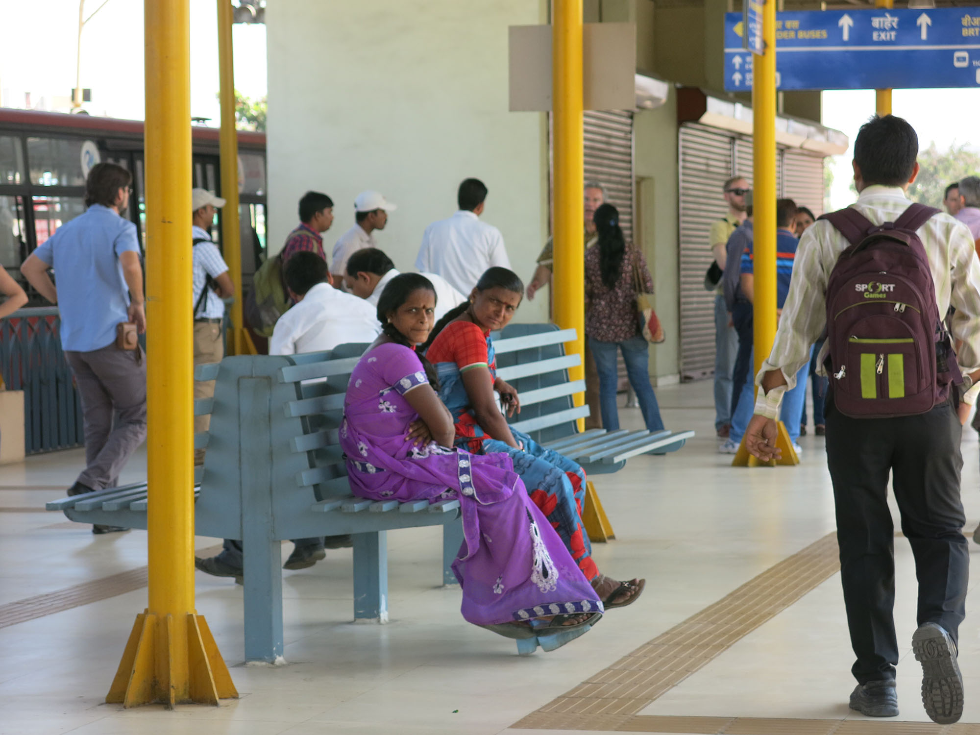
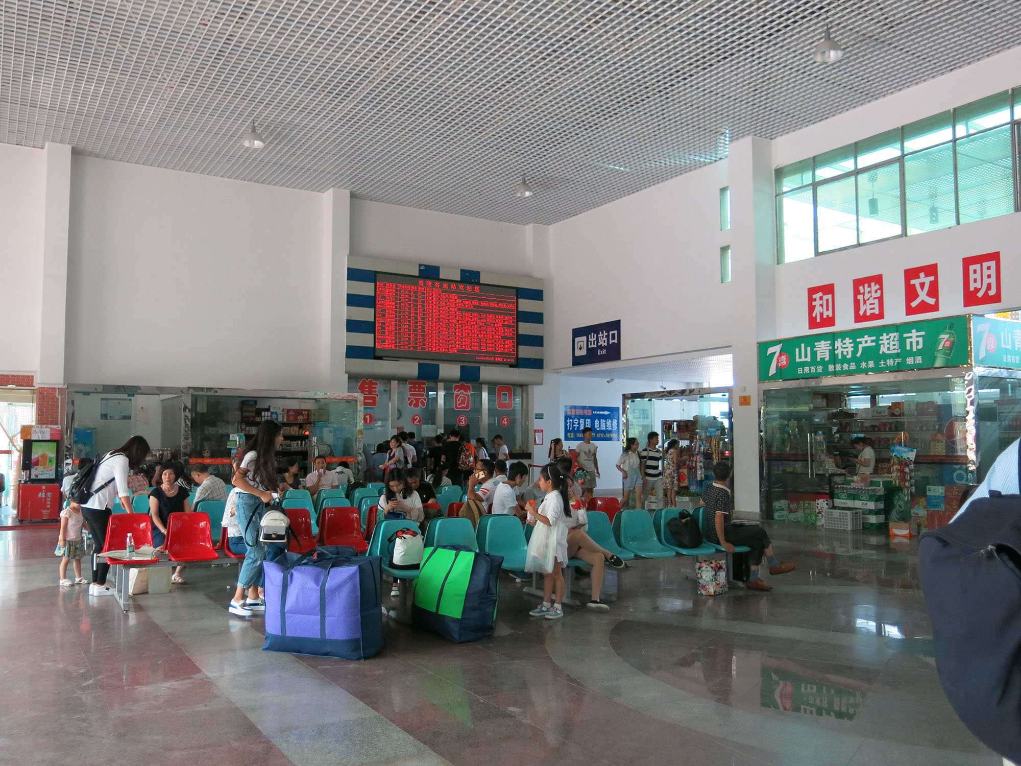
- Seating and waiting lounges. Providing seats is important for the elderly even in high-capacity mass transport stations, such as subway platforms and concourses. For longer-distance travel terminals, such as train stations, long-distance buses and airports, sufficient seating must be designed in the waiting lounge to accommodate the majority of waiting customers according to the demand forecast. Seating should be as close as possible to the boarding area;
- Restrooms. Restrooms are essential in larger intermodal terminals, especially ones serving long-distance traffic (see related item: Cleanliness)
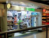
- Retail. Retail is both a welcome amenity to customers and an important source of income to the operator. This may include convenience stores, packaged food stores, dry cleaners, flower shops, and other pick-as-you-go retailers. Larger terminals, especially ones serving long-distance traffic, also require food and beverage outlets;
- Facilities in Long Distance Terminals. Patrons at long-distance terminals benefit from children play areas, VIP lounges, business centers, internet kiosks, and culture-specific facilities such as prayer rooms.
28.1.2.1Internal Intermodal Connections
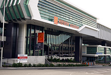
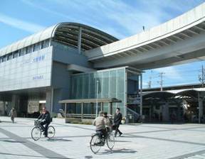
The design of terminals, stations, and stops contributes vastly to the intermodal integration. Metro stations and airports are designed for seamless transfers between lines and planes and the same is true between modes. Wayfinding, ease of ticketing, sufficient walkway width, and other aspects are imperative. A classic example is Hong Kong’s airport where the different modes (plane, bus, taxi, train, ferry) are stacked vertically. Access is accomplished via gentle ramps and escalators. Berlin’s Hauptbanhof (main train station) is similarly stacked vertically. São Paulo’s Metro terminals have large ramps connecting the trains and BRT.
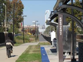
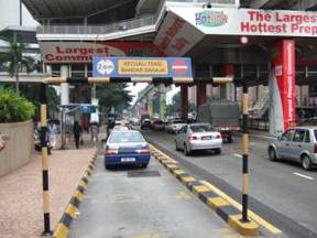
Pedestrian Facilities
Transport hubs need to be integrated within the surrounding pedestrian network. Multiple points of entry should facilitate direct access from surrounding streets and abutting commercial developments. This may occur via bridges or tunnels, covered walkways, or simply high-quality sidewalks and crosswalks. The general idea is to "extend" the transport station outward. This increases passenger comfort as they "feel" they are in the station sooner. One caveat is that pedestrian bridges and tunnels tend to distract from the overall surface-level walking experience. They should only be used in high volume situations where physical separation is desired for flow control. See Chapters 29 and 30 for more information.
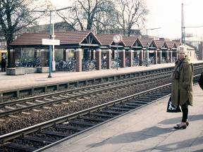
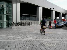
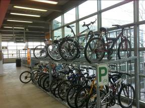
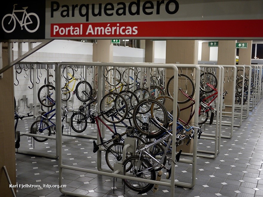
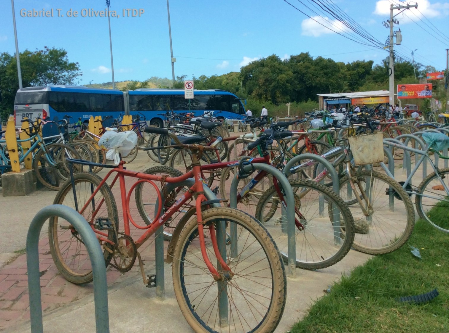
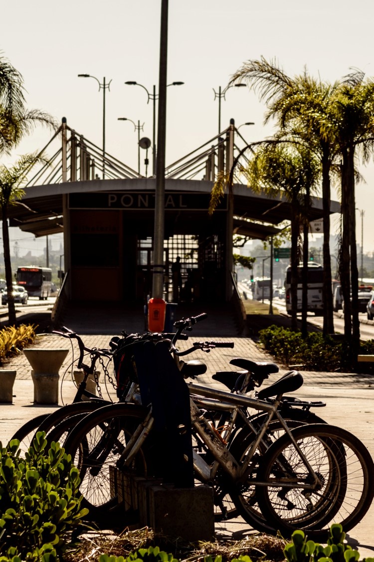
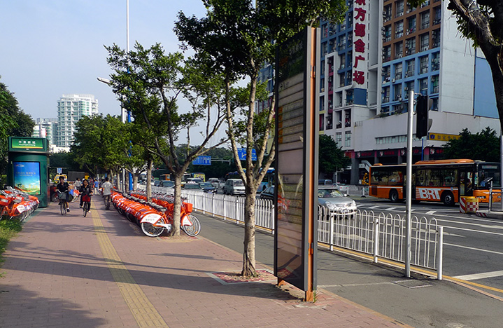
Bicycle Facilities
Bicycles are a viable part of the public transport mix, and progressive transport agencies are integrating facilities for bicycling at a rapid pace. This includes bicycle parking, bike sharing (public bikes), bike taxis, bike routes, and bike stations. Investments range from small, such as bike racks to large, such as bike ramps directly into terminals. In that the physical space needed to accommodate high-quality bicycle transport is so much smaller than that needed for auto transport, the economic benefits are clear. To wit, the bike to car parking ratio is 10:1. See Chapter 31 for more information.
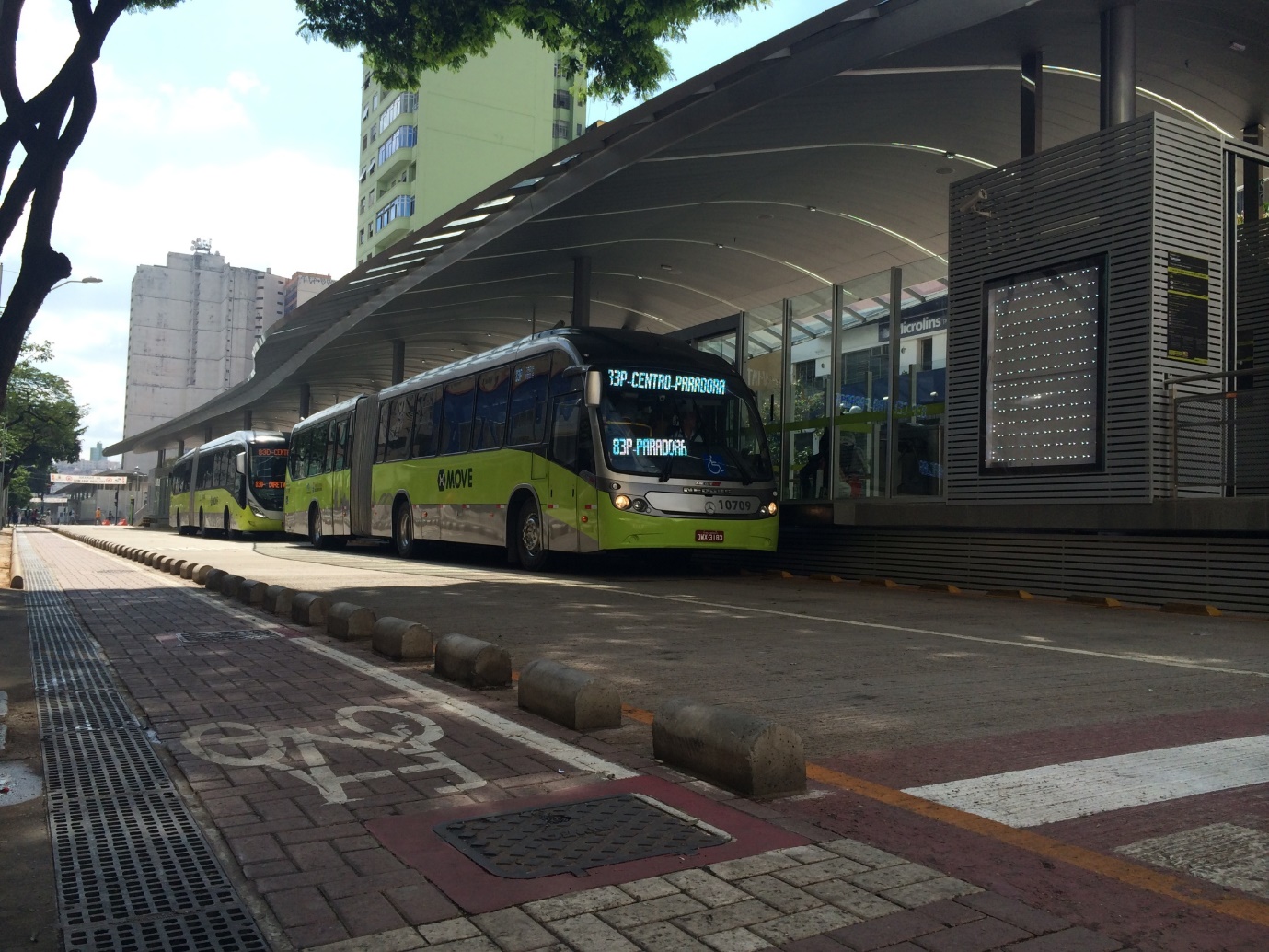
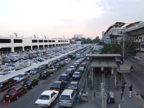
Non-BRT Bus Facilities
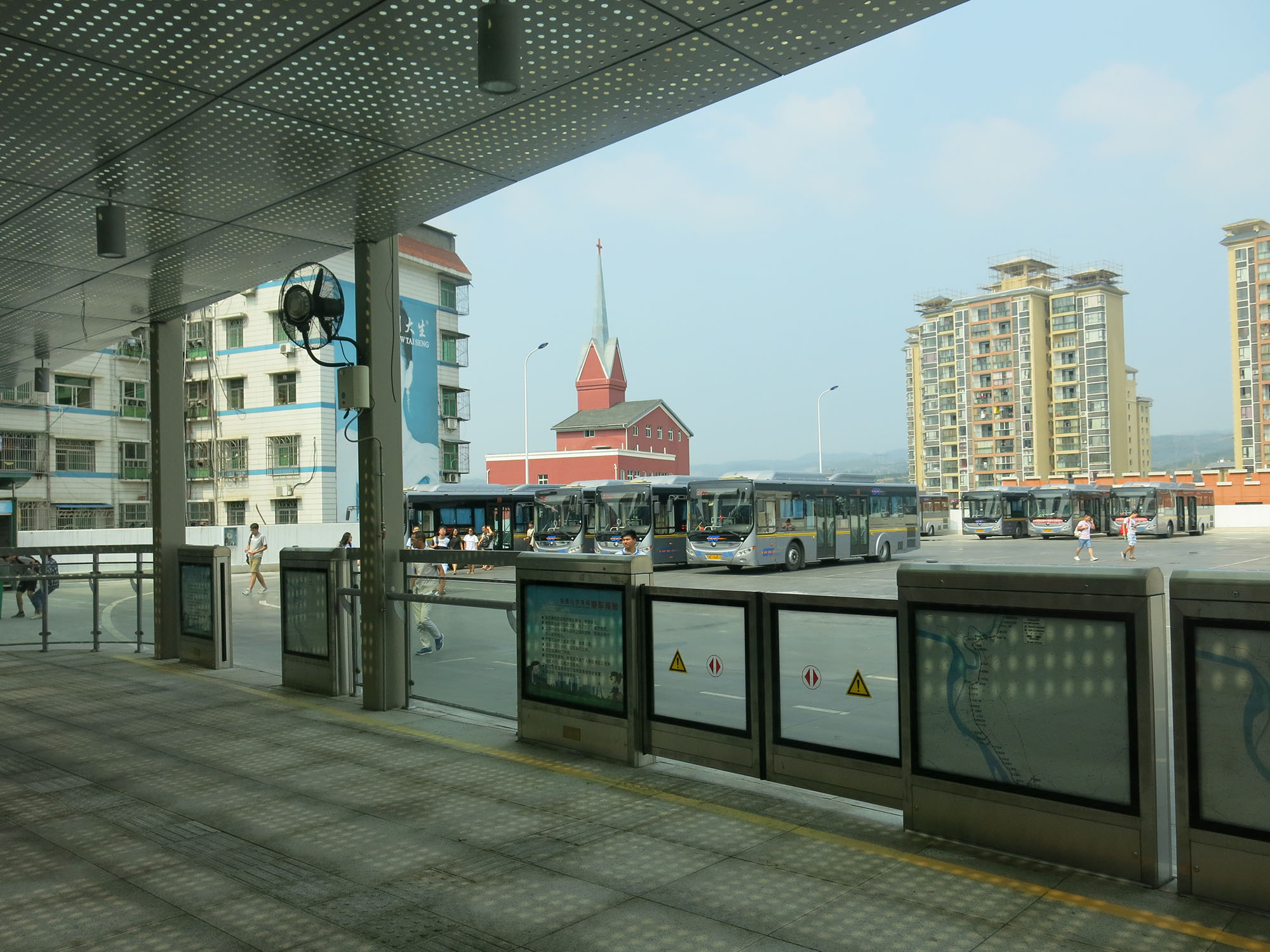
Buses, especially when parked or idling, are an environmental nuisance. When bunched together, they block street-level views and generate significant noise and pollution. As much as possible, bus terminuses should be located so they do not abut major pedestrian routes and in particular public open space.
Four principles of bus facility design:
- Pedestrians first. Pedestrian safety and convenience is the highest priority within and around a bus terminal. At-grade crossings are preferred to pedestrian bridges or underpasses. As much as possible make the buses make the level changes, not the people.
- Parking bay design. Bus loading/unloading bays are ideally operated independently. The most common solution is a sawtooth arrangement or a stacked arrangement for a single route.
- Smooth integration in surrounding traffic. Dedicated ramps, lay-by bays, merging lanes, traffic lights and other transport design features are necessary in order to ensure road traffic to and from the hub moves smoothly and the hub area does not become gridlocked.
- Staging areas. Sufficient provisions must be made for the staging of buses. In dense urban areas, staging may need to be provided in a different site, with on-time dispatch to the pick-up area.
Taxis
Too bad all the people who know how to run the country are busy driving taxi cabs and cutting hair.George Burns, comedian, 1896 – 1996
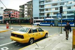
Taxis and other semi-private transport, such as auto-rickshaws, are necessary to extend the reach of transit, especially for those who need to travel long distances, have heavy parcels, or are disabled. It is best to locate parking for taxis and paratransit either within the station, or directly adjacent. By developing integrated taxi facilities in conjunction with BRT stations and terminals, multiple benefits can be achieved.
Developing taxi stands at public transport stations reduces the need for taxi drivers to operate without customers. Instead, the customers come to the taxis rather than the other way around. The strategic location of taxi stands in close integration with BRT stations can thus prove to be a win-win for system designers, taxi drivers, city officials, and the public. System designers win by adding another important feeder service to their route structure and taxi owners and drivers win by dramatically reducing their operating costs. The BRT stations provide a concentration of customers for the taxis without the need to circulate the city expending large quantities of gas. City officials win by helping to reduce a major factor in urban traffic congestion. And finally, the public wins by having a more flexible and convenient public transport system that also reduces urban emissions and promotes greater overall efficiency.
Modern vehicle designs, escalating fuel prices, and growing environmental concerns have led to a resurgence in pedicabs in many parts of the world, especially in the Western European cities of Berlin, Copenhagen, and London. Pedicabs can make for an almost ideal feeder service to BRT stations, especially trips of four kilometers or fewer. Pedicabs are low-cost vehicles that provide high levels of employment while producing zero emissions. See Chapter 31 for more information.
Box 28.2 Taxis without passengers may add to congestion
In many cities of the world, and especially in developing-nation cities, taxis represent a large proportion of the vehicles on the road at any given time. However, taxis spend much of their time in search of customers rather than providing actual customer trips. Prior to the introduction of improved taxi ranks and dispatch systems, taxis in Shanghai were estimated to spend eighty percent of their travel time without customers. Thus, these non-customer trips can add greatly to congestion levels without serving any real purpose. This, however, may be changing with taxi-ordering apps such as Uber, EasyTaxi, and others, but it is unclear if this is the case or if these will increase congestion.
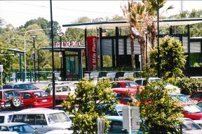
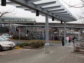
Park+Ride and Kiss+Ride Facilities
Park+Ride and Kiss+Ride are not really recommended for the land adjacent to transit systems. Generally, park and ride presumes low land value around transit while high quality transit generates high land values (Jarrett Walkerr,Basics: The math of park and ride http://humantransit.org/2014/10/basics-the-math-of-park-and-ride.html). Park and rides will ultimately be a constraint in increasing ridership on transit, as once it is built it is hard to remove. The land is more usefully used to house people and have services nearby to transit. It is preferable to devote some space for Kiss and Ride and connections to intermediate modes of transport that can be shared as opposed to private car use. These include bike share, ride shares, shared taxis, three-wheelers. Thus, park and ride is really only recommended for suburban and rural areas, if at all.
Park-and-ride facilities provide secure parking for cars in a garage or lot. Kiss-and-ride facilities provide pick up and drop off for customers immediately adjacent to the station entry.
Park-and-ride and kiss-and-Ride are only recommended for terminal stations in suburban and rural areas where population densities are insufficient to justify feeder services and/or distances are too far to make direct walking and cycling access to the station viable for most people. These conditions will primarily be found in neighborhoods dominated by affluent households that have sufficient disposable income to own a private vehicle. Attracting this income group to the public transport system can deliver several benefits.
- Offsetting private vehicle use pays significant dividends in terms of emission reductions and congestion relief;
- A public transport system that is of sufficient quality to attract even the highest income groups is a worthy objective;
- A healthy mix of all a city’s income groups in the system means that all political interests will have an incentive to ensure the system’s future;
- Systems, which serve all income groups, also serve an important social function since the public transport system may be the one location where all segments of society come together.
Park-and-ride and kiss-and-ride are not recommended in downtown locations where the parking facility is more likely to be used to drive into the downtown. Private vehicle owners are less likely to use a park-and-ride facility if they are driving a substantial distance into the city and then using the public transport only for a small final portion.
The location of the parking facility should be convenient to the station area. A long walk may discourage usage from discretionary customers. In cities with frequently unseasonable weather (wind, rain, strong sun), covered walkways in the parking area may be a worthwhile investment. In some areas, it will be necessary to include security measures at the parking facilities. Security measures such as an attendant or security cameras can be effective. If security is insufficient, motorists will choose to use their private vehicle for the entire commute.
Whether motorists should be charged for parking at a park-and-ride facility depends on the location of the facility and the set of incentives in place. Subsidizing parking for higher income motorists far from the city center can be justified because it will encourage motorists to make a long public transport trip, reducing significantly the congestion and air pollution that would otherwise have resulted from the trip. The closer the park-and-ride facility is to the city center, the less the social benefit, and hence the weaker the justification for a public subsidy.
Parking facilities can be quite costly to develop and construct. Each at-grade parking bay may cost US$3,000 to US$15,000 when land purchase costs are included. Each parking bay within a multi-level parking facility will likely cost in the range of US$20,000 to US$35,000. Costs can be even greater in areas with significant land costs. Thus it can be necessary to establish a fee for use of parking facilities at public transport stations. The challenge is to develop a fee structure that still provides a strong incentive for using the public transport system.
Box 28.3 Locating a parking garage or lot immediately adjacent to a transport station can be problematic
- The land may be more suitably integrated with other active uses such as civic places or public amenities;
- People arriving to the station by foot or bike have to walk or cycle through the garage or lot, which makes the journey longer;
- Introducing private vehicles into the station area decreases safety;
- Buildings typically produce more rental income than garages or lots;
- Prioritizing drivers is counter to the aims of public transport.
The preferred solution is to build a parking garage and integrate it into the surrounding building context so that it does not call attention to itself.