23.4Roadway Pavement Design
You know more of a road by having travelled it than by all the conjectures and descriptions in the world.William Hazlitt, literary critic, 1778–1830
The construction of the busway will typically represent approximately 50 percent of the total infrastructure costs. Thus, savings through efficient design and material choice can produce significant dividends. Cost savings, though, must be viewed both from the perspective of initial construction costs and long-term maintenance costs. Lower-quality road materials may reduce capital costs, but will dramatically increase maintenance costs if roadways need repaving or reconstruction after just a few years.
23.4.1Alternative Pavement Treatments
The principal determinant in choice of roadway materials is the axle weight of the BRT vehicles selected for operation and the number of projected BRT vehicles likely to use the infrastructure over the projected service life of the road. The roads must be built to a standard able to withstand the projected usage by vehicles with the specified axle weight. One pavement treatment that works well in temperate climates may degrade in tropical climates. Local pavement engineers should thus be a part of the decision-making team.
If the BRT vehicles are standard 18.5-meter articulated vehicles, they may require reconstruction of the entire roadbed with materials able to withstand these heavy axle loads. The total vehicle weight of the articulated vehicle utilized by the Bogotá TransMilenio system is approximately 30,000 kilos, and the maximum axle load is approximately 12,500 kilos. The vehicle volumes are also extremely high, so busways must thus be constructed to withstand this axle load on a frequent basis.
The weight of the vehicle is most acutely experienced at stations, where the vehicle’s acceleration and deceleration increases the amount of force on the roadbed. The degradation of the roadbed from the weight and force of the vehicles is also a more serious problem at stations, where it can effectively render a station boarding area inoperable. As the roadbed level lowers, the station-to-vehicle interface will no longer align evenly and a step will form between the vehicle floor and the platform.
There are several options for the pavement structure with advantages and disadvantages for each. The following are three of these options:
- Asphalt: Properly designed and constructed, asphalt pavement can last more than thirty years with surface replacement every ten to twelve years. This can be done without interrupting service, resulting in a smooth, quiet ride. For stations, rigid pavement is important to use to accommodate the axle loadings due to loaded buses and resist the potential pavement damage due to braking;
- Jointed Plain Concrete Pavement (JPCP): This type of pavement design can have a life of thirty or more years. To ensure this life the pavement must have round dowel bars at the transverse joints, tied lanes by the use of reinforcing steel, and adequate thickness;
- Continuously Reinforced Concrete Pavement (CRCR): Continuous slab reinforcement can add additional pavement strength and might be considered under certain design conditions. It is the most expensive option.
Asphalt pavement that is correctly designed can be a cost-effective alternative that provides the quietest and smoothest surface for BRT. The top layer (two inches) can be ground off after ten years and repaved. This can be done while service is maintained by doing the work in hours when the facility is closed. It can be ground down and still be used while the new paving takes place late at night. The asphalt alternative will still need concrete pads at the stations.
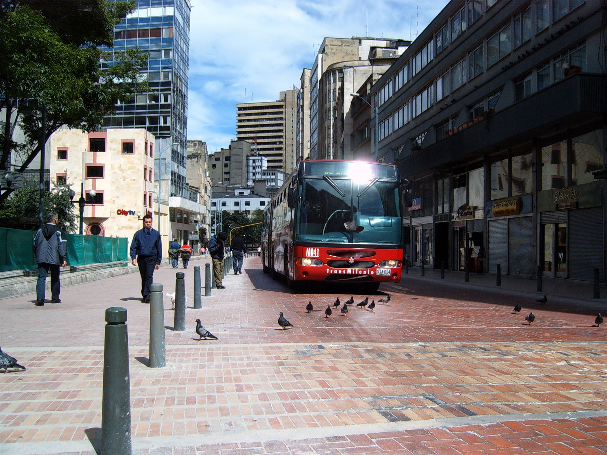
Other building materials can also be used, though they tend to be more expensive. Particularly in the city center, brick and other paving stones are frequently chosen for aesthetic reasons (Figure 23.8). These surface materials also send a useful visual signal to bus drivers that they are in a public space and must operate at safe speeds. Such materials are often able to withstand very heavy axle loads with regular maintenance.
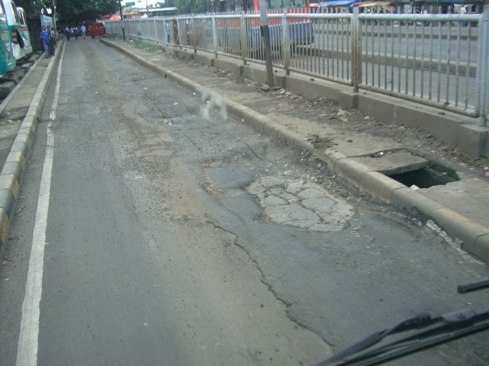

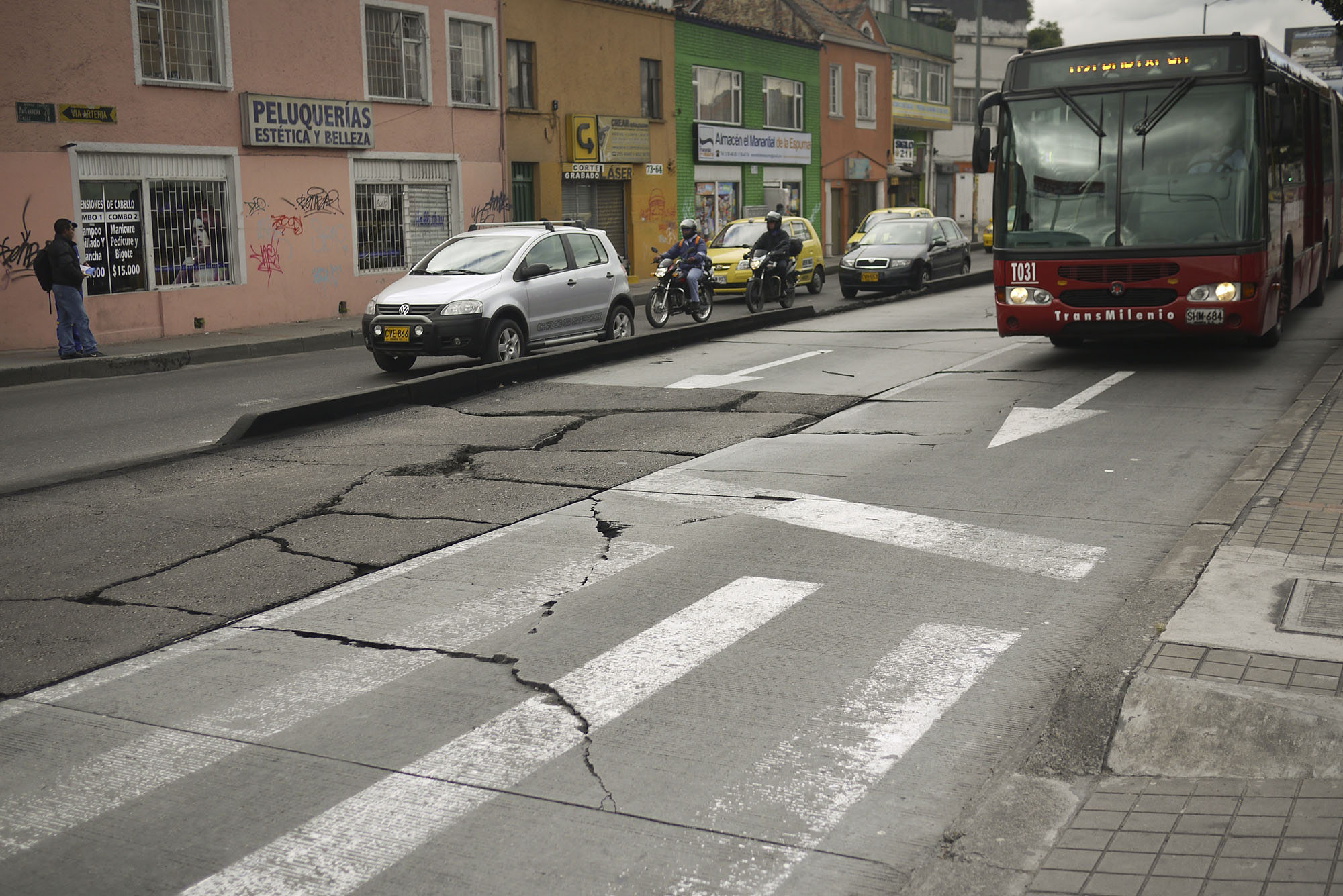
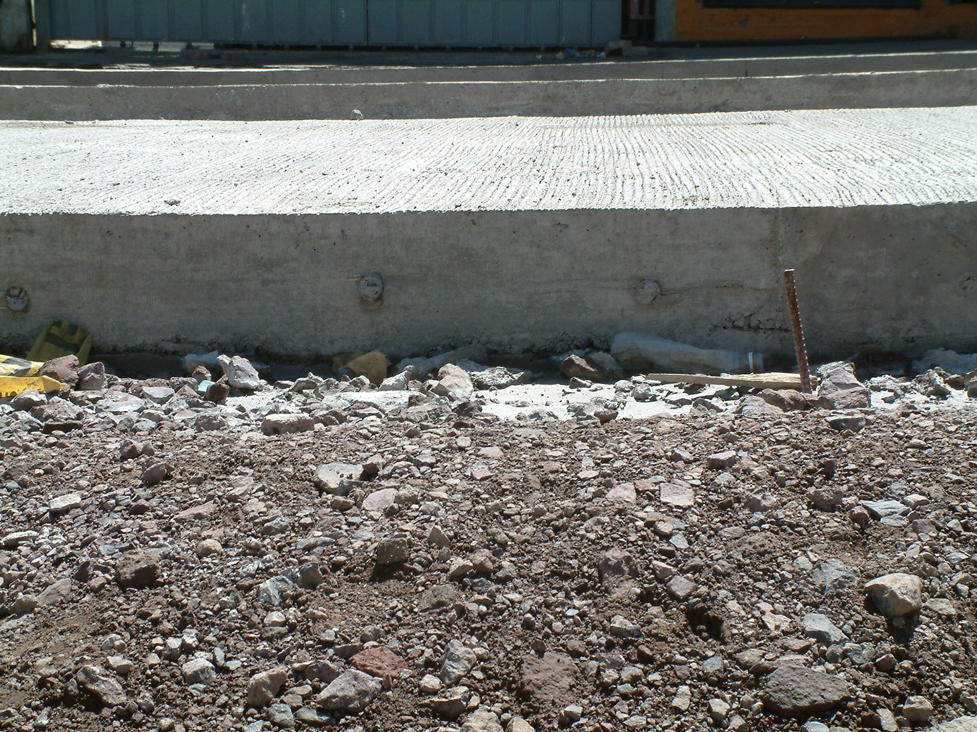
The surface material will only endure as long as the base materials are intact. If water drainage is insufficient or if the base structure is inherently weak, then the surface material will quickly fail. A poor base design in Bogotá led to the premature failure of the concrete surface on the system’s Avenida Caracas corridor. Bogotá has largely relied on a technique known as “white topping” for its concrete busways. The white topping method utilizes the existing asphalt lane as the base material for the concrete surface material. White topping is thus a fairly economic option since it does not rely upon reconstruction of the busway base. However, the successful application of white topping depends on the strength of the base core, the integrity of the asphalt layer, and the level of cohesiveness between the asphalt and concrete layers.
23.4.2Pavement Design
Pavement design must be preceded by investigations and assessments of the route through a center-line soil survey and an analysis of the existing ground conditions on-site. Further information is required on the prevailing climate, environmental implications, and geology. The availability and cost of materials such as bitumen and pigments for colorization may guide or influence the more detailed design elements. Once the design procedures for each type of pavement have been considered, a number of designs, excluding any potential variables, may result. Cost considerations may now be used to further the decision-making process.
The above process leads to a basic design of the layers for each pavement option, and this can be described as a virtual catalogue of the details of each pavement option. This product is essentially a series of drawings of how the layer works for each pavement option with a detailed description of each layer.
Pavement joints are usually associated with concrete rather than asphalt pavements. This distinction is relevant when the layer design has progressed to the level of layout adaption. The type of jointing employed on the rigid concrete pavements is determined by the layout design.
Asphalt pavements or interlocking pavers do not require jointing, as they interact with various obstacles in a more flexible manner than rigid concrete. Flexible asphalt flows around corners and curves and does not expand or shrink, while concrete will cause difficulties if not designed with joints. Joints may be designed in a variety of ways to suit the local requirements.
The only viable options for flexible pavements are asphalt or interlocking pavers, while rigid pavement designs offer a wide range of variations to accommodate different design philosophies. Jointed concrete pavers or continuously reinforced concrete are only two of the examples of rigid pavement, but jointed concrete pavers are not ideally suited to the long straight lengths of roadway usually associated with BRT systems.
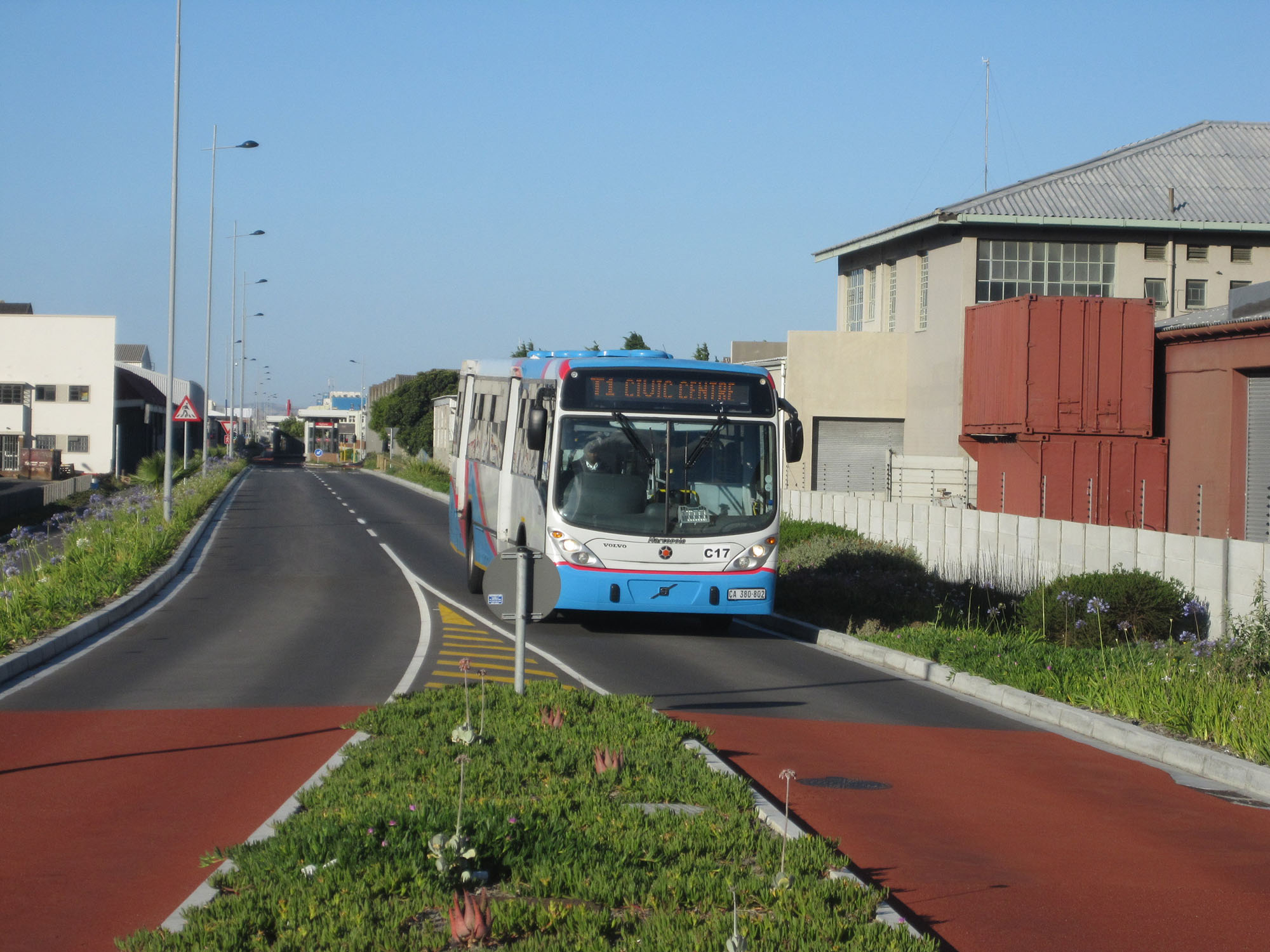
Color or texture differentiations can be applied to any type of design. The colorization of asphalt may occur through the application of a color layer or the final surface itself may be colored. The MyCITI system in Cape Town, South Africa, has experimented with limited sections of colored friction course applied over the asphalt layer on certain routes (Figure 23.12). The longevity of this type of surface treatment will be evident only through future evaluation.
Although concrete block pavers are not recommended for BRT routes, this type of surface treatment is usually colored and can then be used very effectively in demarcating non-motorized routes or intersection details.
Concrete is colored through the addition of pigmentation. The selection of a specific color and the level of pigmentation should be based on a certain level of performance record.
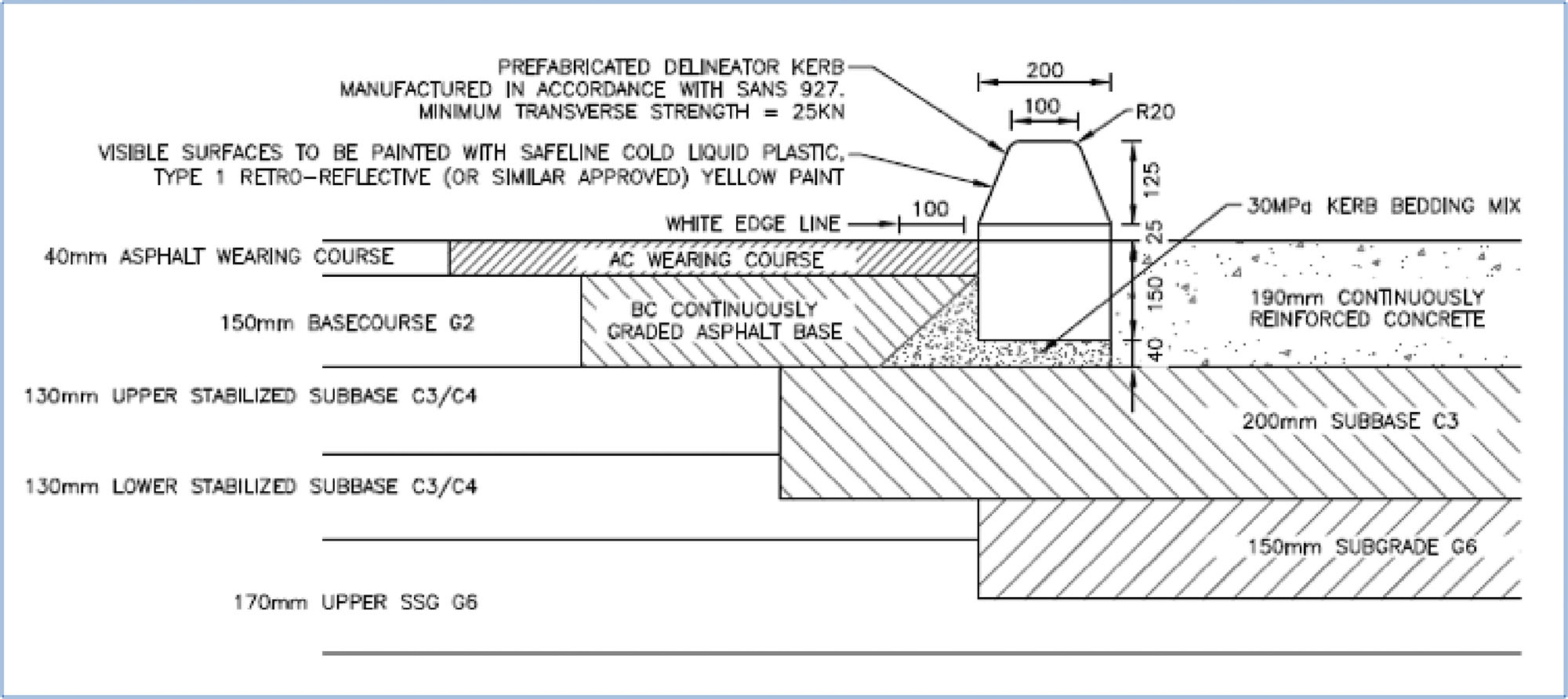
The design and function of continuously reinforced concrete (CRC) pavements is based on the placement of high-tensile steel predominantly in the longitudinal direction of a concrete pavement with minimum transverse steel. The main steel is placed in the center of the concrete thickness and is sized and spaced during design, along with the concrete thickness, strength, and pavement supporting layers, to limit the occurrence of distress in the forty-year design period under the specific loading to national distress standards that are contained in the software.
In the case of the BRT, the loading is the combination of approximately 12.5-ton main axles from both the 18-meter and 12-meter vehicles, as well as the approximate 7.5 tons from the steering axles. The pavement distress that is both limited and controlled during the design procedure is mainly the shattering of slabs (to around 2 percent) and the controlling of the transverse-shrinkage cracks to between 1- and 2-meter spacing over the entire pavement length.
Because of the lack of constructed-transverse joints over the pavement-lane length of concrete, which is approximately 3.7-meters wide, the concrete shrinks after placement. With the controlling influence of the longitudinal main steel, the transverse cracks (which are expected) form at approximately 1- to 2-meter spacing. These cracks are through the concrete full depth, but are kept tight by the longitudinal steel, which holds the entire system together. These cracks are not typically sealed by design.
At intersections where the CRC pavement lengths end, a series of end beams and floating slab panels are constructed to add friction to the support and to absorb small movements in the panel joints, which are dowelled and sealed.