30.6Vehicles
The higher we are placed, the more humbly we should walk.Marcus Tullius Cicero, philosopher and politician, 107 BC–43 BC
This section discusses accessibility features of BRT trunk-line vehicles and feeder buses.
Feeder bus lines that are carefully integrated into larger BRT trunk lines are more likely to be operated in an accessible manner. Sometimes called “complementary buses,” they are found in several cities, such as Cali, Colombia, and Johannesburg, South Africa. Typically, a single vehicle design is chosen that can exhibit accessibility features such as audio and visual on-board signage and, to different degrees, access for those who cannot climb steps. They have high doors on one side for use at trunk-line stations and low doors with steps, supplemented by ramps or lifts, for use at curbside stops, where the buses operate in mixed traffic.
A different challenge presents itself if feeder bus lines are cannot climb steps. They have high doors on one side for use at trunk more difficult for such a system to consistently exhibit the driver training, audio and visual signage, minimal vehicle-to-curb and vehicle-to-platform distances, and so forth.
30.6.1Low -Versus High- Floor Vehicles
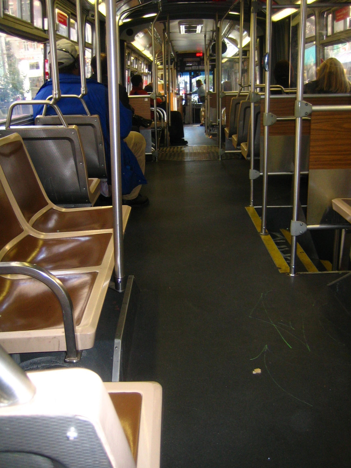
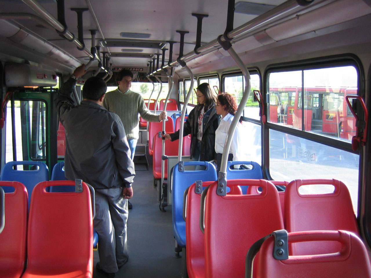
From an internal accessibility standpoint, a standard layout is preferred: one level floor, straight aisle, simple seating plan, seats of a uniform height. This regularity makes the vehicle more accessible for customers in wheelchairs and with disabilities. High-floor vehicles, because the wheels lie beneath the seats, generally use this standard layout.
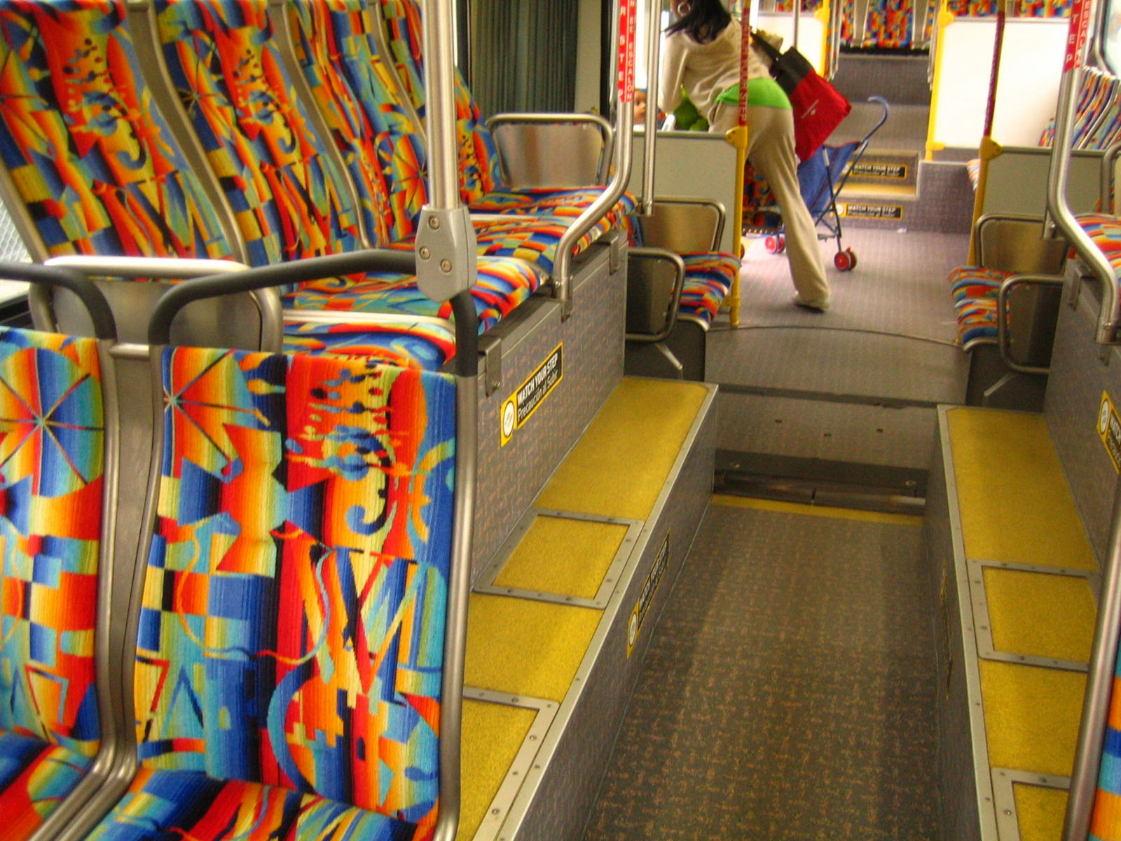
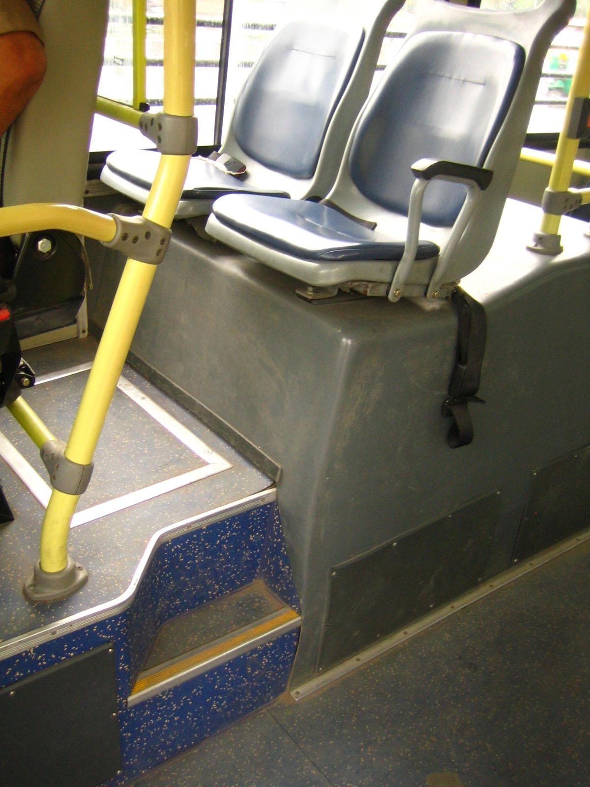
Low-floor vehicles, while easier to board from the street, generally have an interior design that is less accessible. There are usually multiple levels with steps or ramps between; the aisles tend not to be straight; the seats are at irregular heights; and a person in a wheelchair is typically constrained to a single location. This irregularity degrades accessibility, especially when the vehicle is crowded.
While any vehicle can be made minimally accessible, the goal should be to ease use for all. Similarly, vehicles with unusual seating plans may create interest, but if the design detracts and dissuades use, then it loses credibility.
Table 30.3Summary of Internal Accessibility Issues with High- and Low-Floor Vehicles
| High Floor | Low Floor | |
|---|---|---|
| Floor Level | Generally one level | Multiple levels, steps, and ramps problematic |
| Aisle | Typically straight | Varies in width, creates obstacles |
| Seating Plan | Simpler, more intuitive | Irregular, leads to the “better” seats taken first, which may force people with disabilities into seats that are harder to access |
| Doors | Possible to have additional doors | Typically constrained by seating layout |
| Wheelchair securement position | Can be directly across from a door, permitting straight entry with minimal turning movements | Typically constrained by seating layout, which may cause additional turning movements, which retards boarding and alighting |
| Seat height | Generally one height | Irregular heights require more maneuvering |
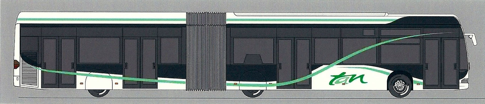
Recent advances in low-floor vehicle design in western and northern Europe may improve accessibility, as vehicle wheel wells and engines have been modified to create less intrusion into the passenger cabin. Several cities in France, including Rouen, Lille, and Paris, now have low-floor BRT systems that appear to perform well for customers with disabilities. A special case is Nantes, France, which is using higher-capacity low-floor articulated vehicles that permit boarding through four doors, thus enhancing customer flows.
30.6.2Internal Elements
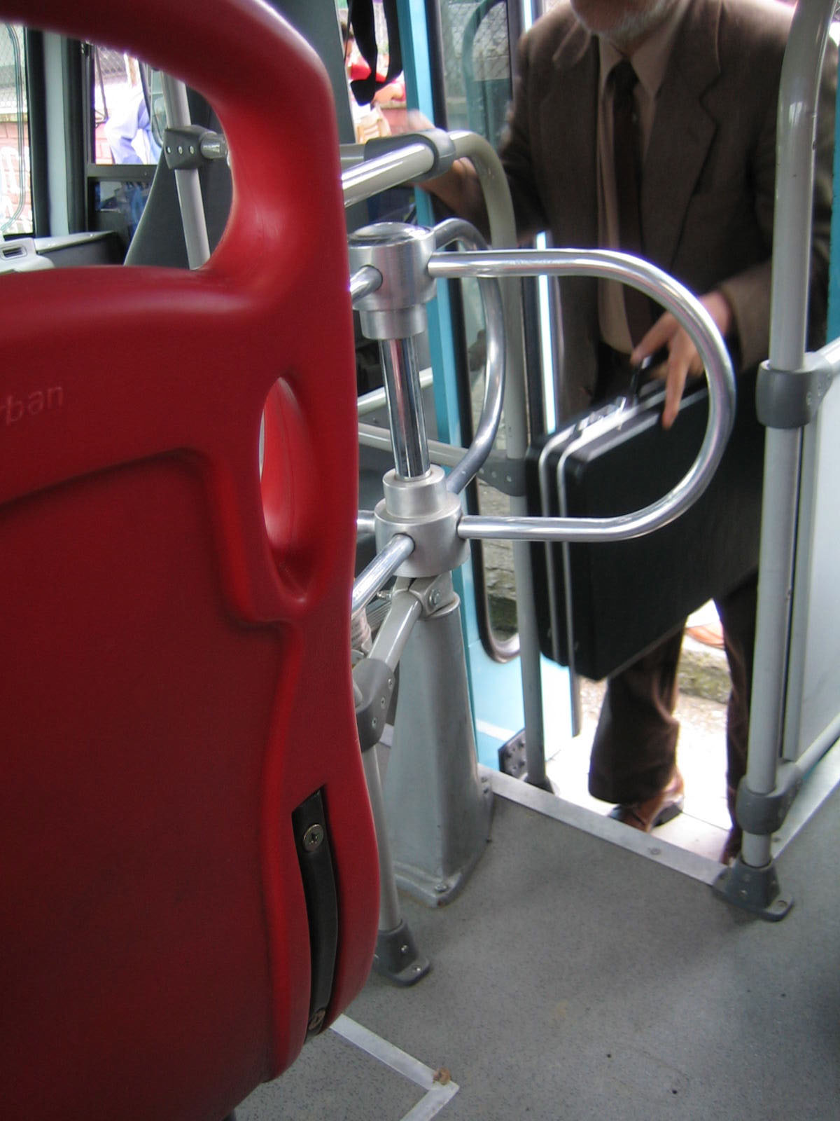
30.6.2.1Hand Grasps
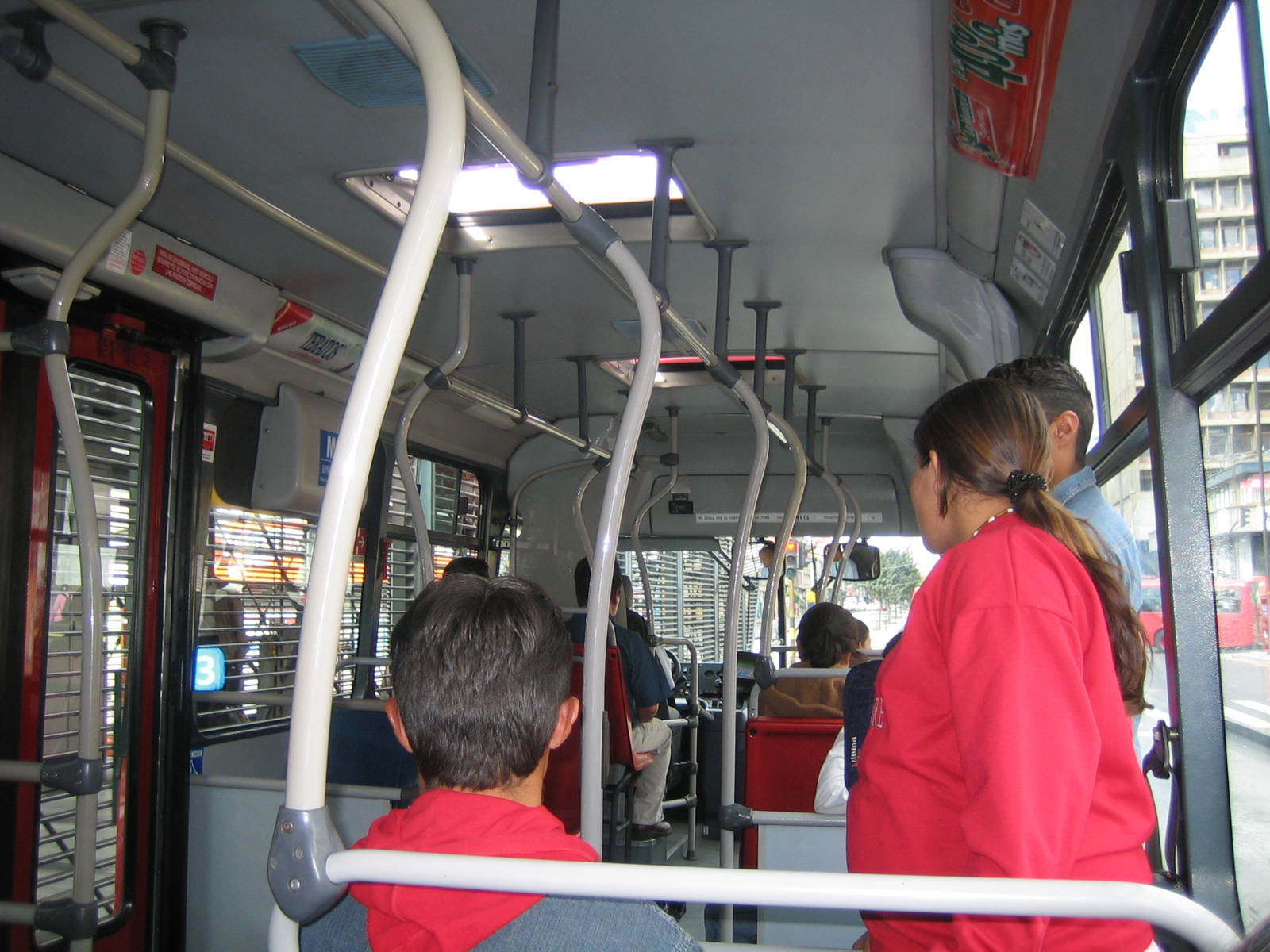
Accessible BRT vehicles have vertical stanchions and horizontal grab bars within reach of all customers. They should be placed so that a person may navigate from one stanchion to another over the length of the vehicle. Ideally this is one per seat, or every 1,050 millimeters, whichever is less. The distance between stanchions should not exceed 1,200 millimeters. Stanchions and handholds should be painted in a contrasting color, typically a bright yellow. Straps hanging from horizontal elements near the ceiling can provide handholds to help customers reach a seat, while vertical stanchions also help shorter persons who cannot reach other handholds.
30.6.2.2Seat Design
It is important for persons with disabilities that seats are surfaced with materials with a coefficient of friction sufficient to prevent customers from sliding back and forth while the vehicle is in motion. Seat surfaces should be ergonomically contoured. Ideal dimensions are noted in DPTAC and COST 349 (MacDonald 2005, pp. 17–18).
30.6.2.3Prioritized Seats
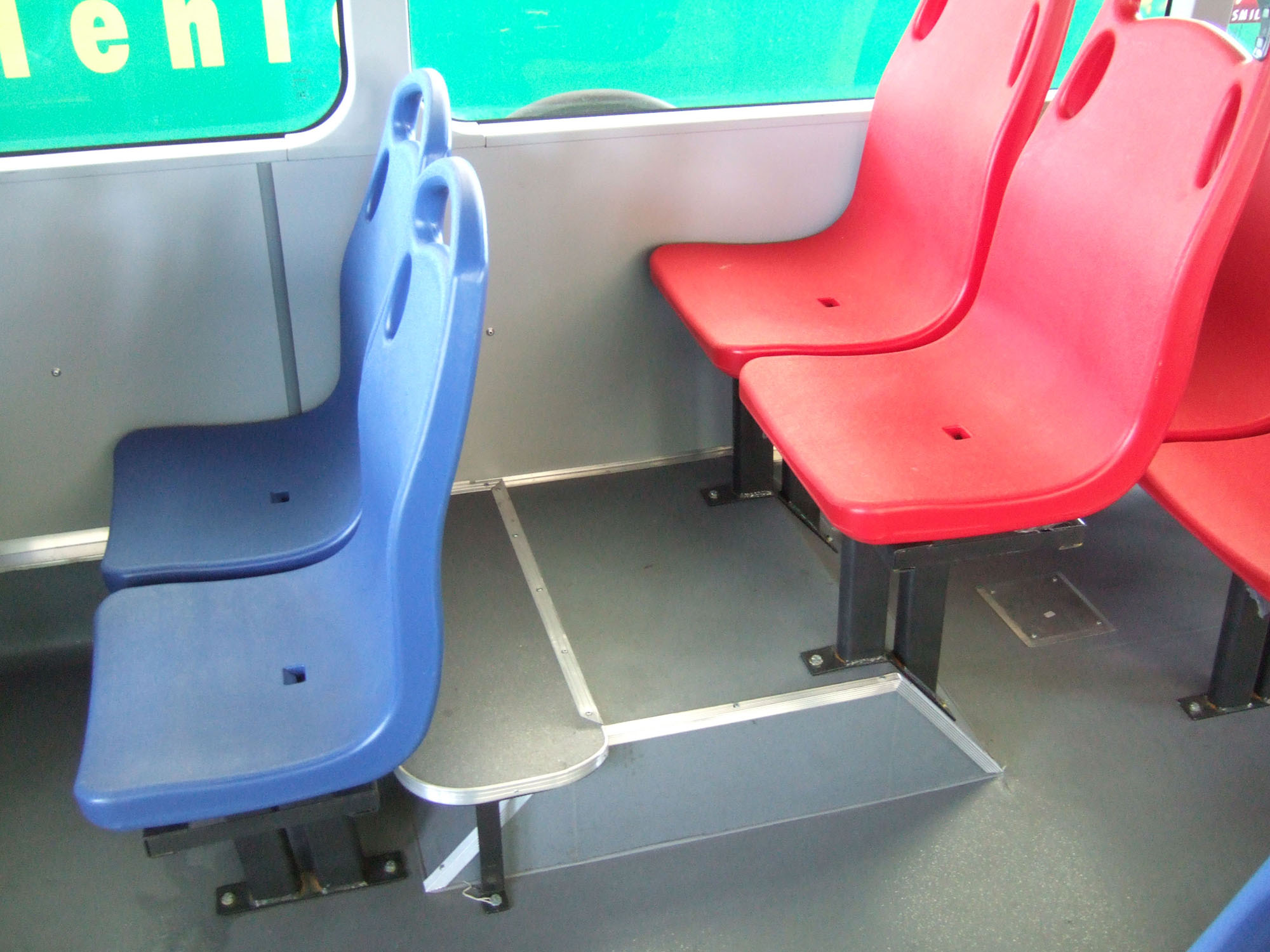
Prioritized seats should be available for persons with disabilities, seniors, and pregnant women. These seats should face the front or rear of the vehicle, not toward the side, to provide more stability when the vehicle starts, stops, and turns. Priority seats require clear signage, adequate space, and should be located near the driver. The area around the seat should provide room to store a mobility aid, such as a folded wheelchair, a walker, crutches, or a “seeing eye” dog guide.
Contrasting colors help identify priority seats. The color should be consistent across the system and should be determined by local preference or mandate.
30.6.2.4Wheelchair Travel Path
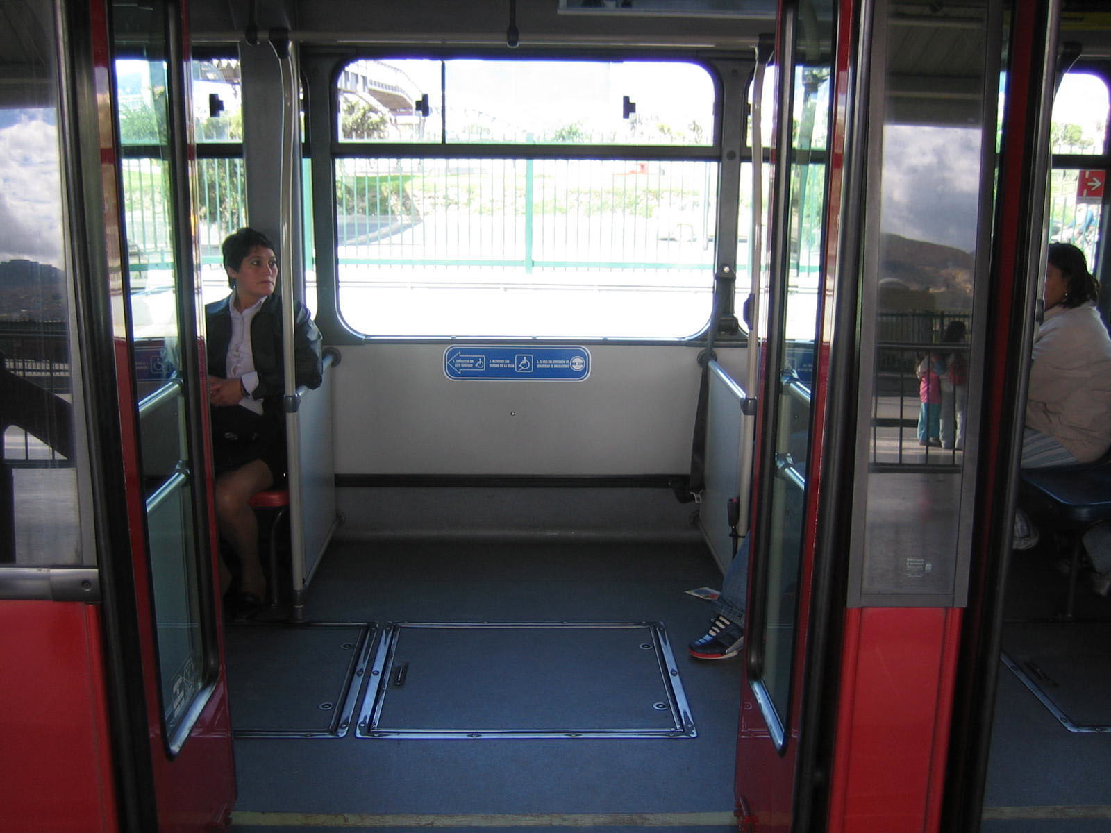
Ideally, securement areas are located opposite doorways to minimize travel within the vehicle. Where there is only one per vehicle, it should be located near the driver. When not in use, it may be occupied by standing customers, folding seats, bicycles, prams, carriages, and so forth.
Standard dimensions (MacDonald 2005):
- Doorway: 850 millimeters wide;
- Clear route from door to securement location: 750 millimeters;
- Turning area: 1500-millimeter circle;
- Securement area: 750 millimeters wide and 1300 millimeters long;
- Unoccupied wheelchair: 700 millimeters x 1200 millimeters.
It is recommended that vehicle vendors be made responsible for wheelchair accommodation. Typically, this is via detailed design drawings illustrating minimum dimensions and travel paths. Ideally, wheelchair users would test a full-size mock-up (including seats, stanchions, fare box, securement areas, doorways, etc.). Wheelchair users vary in their ability to maneuver; a mock-up is useful in understanding how they react to a particular design.
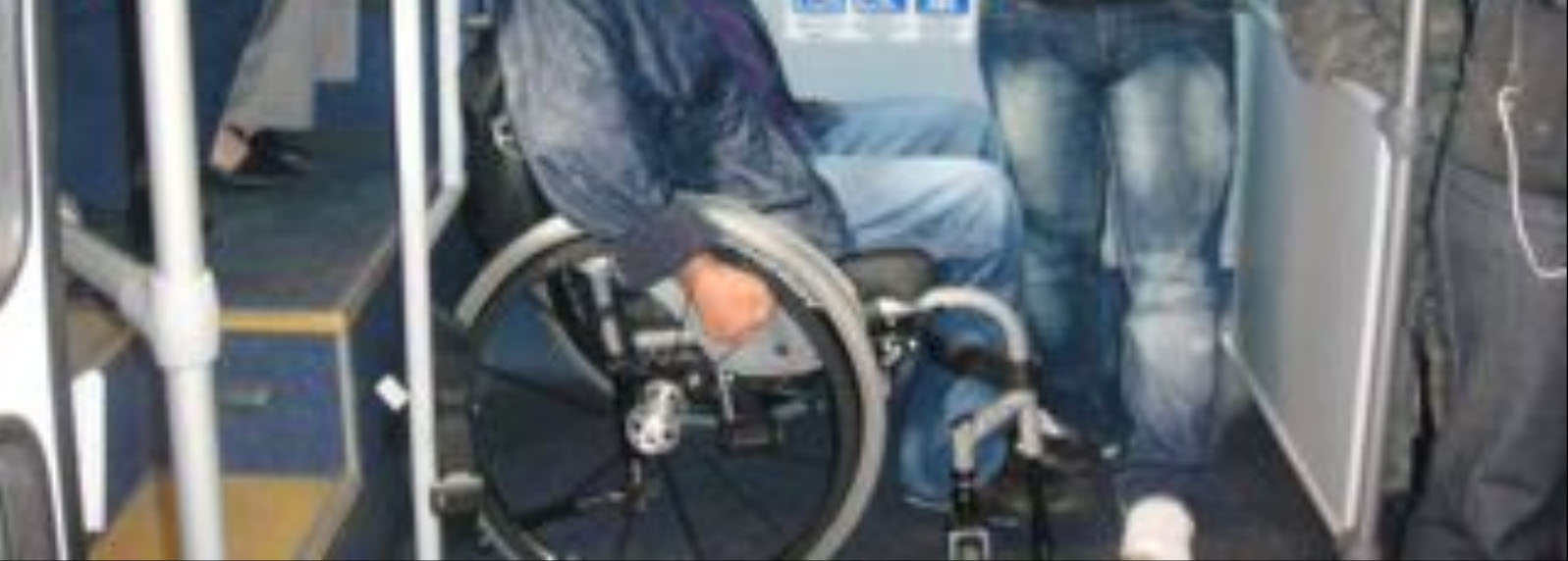
30.6.2.5Wheelchair Securement
Some type of securement system is required. In North America, this is accomplished via a three-point safety belt. The customer is seated facing forward or backward. Typically, a wheel clamp is provided. Additional methods may be needed when the route includes severe inclines. Not only do “tie-downs” secure wheelchair customers, but they also protect others from wayward wheelchairs. In every case, all governing norms and standards for safety should be followed.
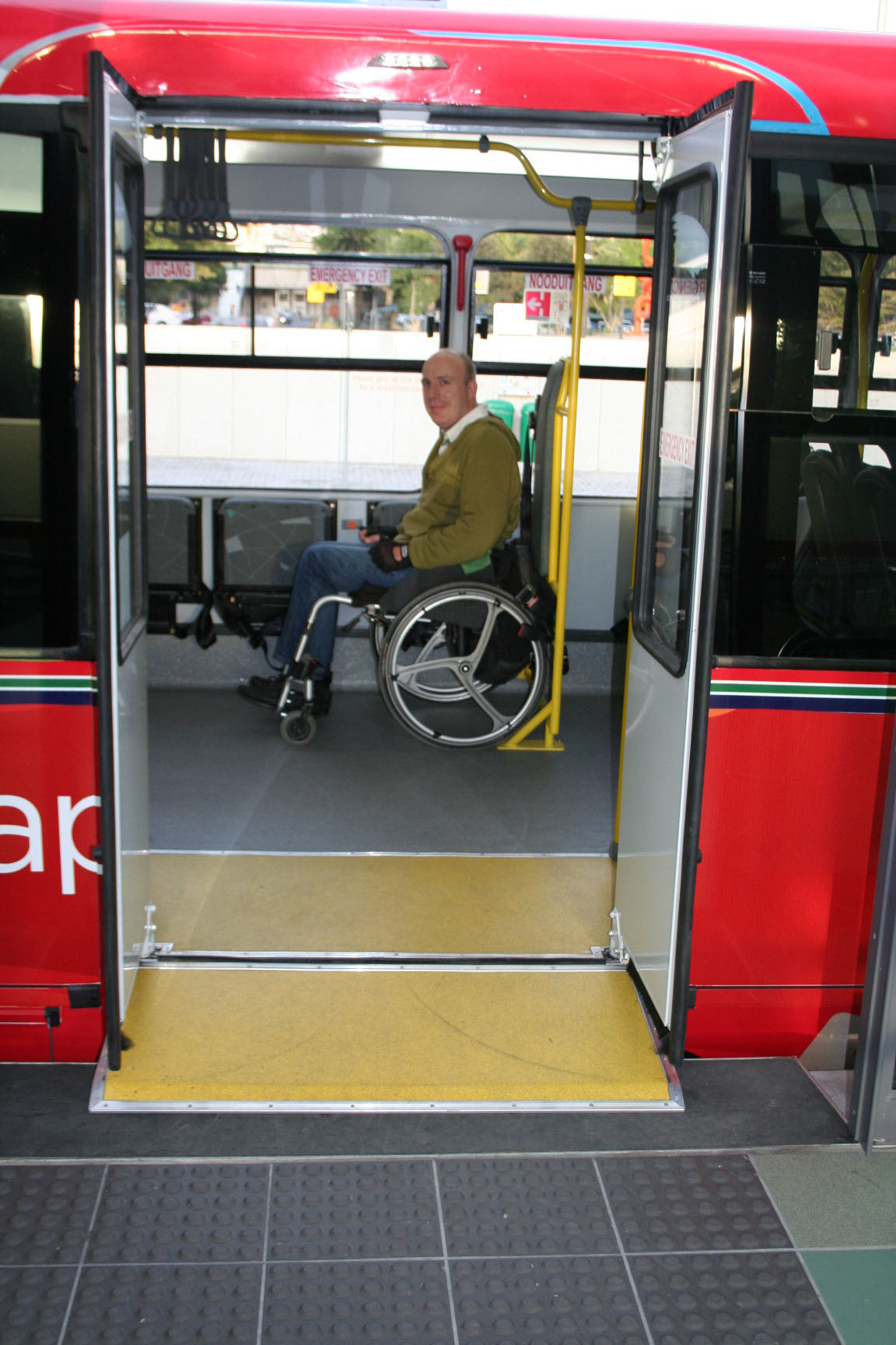
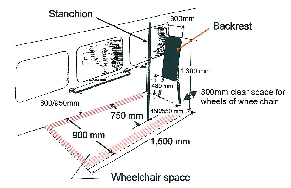
On BRT routes with large vehicles, few hills, and minimal curves, the “tie-down-less” system used in Europe may be preferred (Figure 30.55). It requires that wheelchair riders face the rear of the vehicle, and assumes that drivers are well trained and monitored to avoid sudden stops and starts.
30.6.2.6Turnstiles
Turnstiles in buses are a barrier to many seniors, persons with disabilities, pregnant women, parents with children, and persons with packages. They should be eliminated.
30.6.2.7Stop-Request Signals
Stop-request signals (buttons or cords) are needed on all vehicles that stop on demand (not on the fixed BRT corridor). They especially help customers with sensory disabilities.
Stop cords or buttons should be located near seats. Buttons are generally preferred because they are more easily used by persons with less strength in their hands. A lower cord or button is required within reach of a customer in a wheelchair securement position. The button or cord should activate a sign in front of the vehicle, providing feedback to customers that their request has been received.
30.6.3Signage
30.6.3.1Exterior
All customers benefit from large-print vehicle route and destination signs:
- On the upper front of the vehicle;
- High on the side near the entrance door;
- At the rear.
Signs should be clearly visible with contrasting backgrounds (white or yellow letters against a black background). Increasingly, GPS technology permits automatic stop announcements thereby allowing waiting customers to hear route information as the vehicle approaches a stop or station.
Table 30.4Recommended letter sizes and applications for signage. Adapted from TRL, page 161
| Application | Preferred letter height | Minimum letter height |
|---|---|---|
| Route number on vehicles | 300 mm | 200 mm |
| Route name/destination on vehicles | 200 mm | 125 mm |
30.6.3.2Interior
- Tactile route maps with Braille text should be available for blind customers from the public transport operator;
- Electronic visual displays and audible announcements of the next stop are helpful, including audible warnings when doors open or close at trunk line stations. Signs in raised letters assist blind persons to identify priority seating for customers with disabilities;
- Taking advantage of advances in smartphones and other electronic location systems will make the BRT more accessible.
30.6.4Vehicle Access
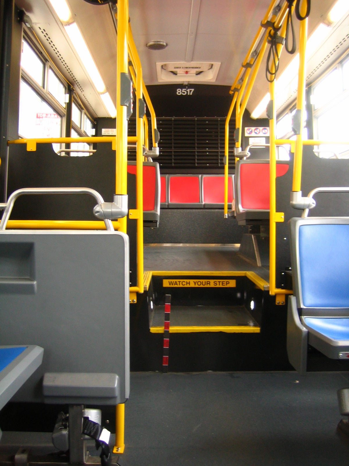
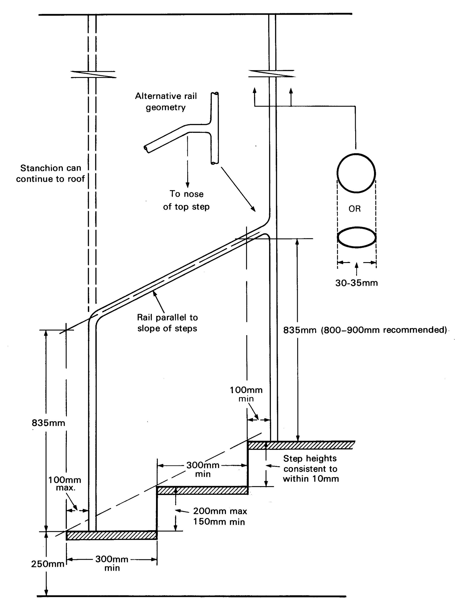
30.6.4.1First Step and Handrails
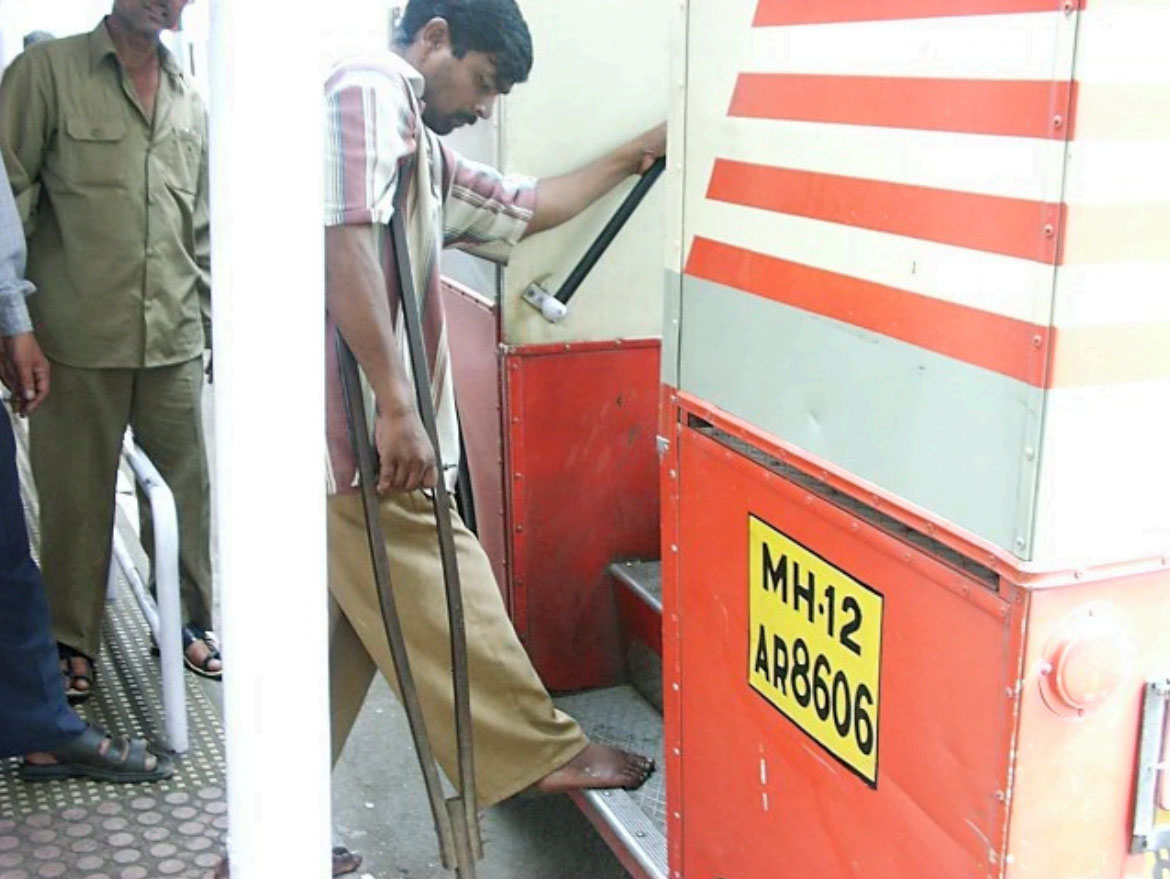
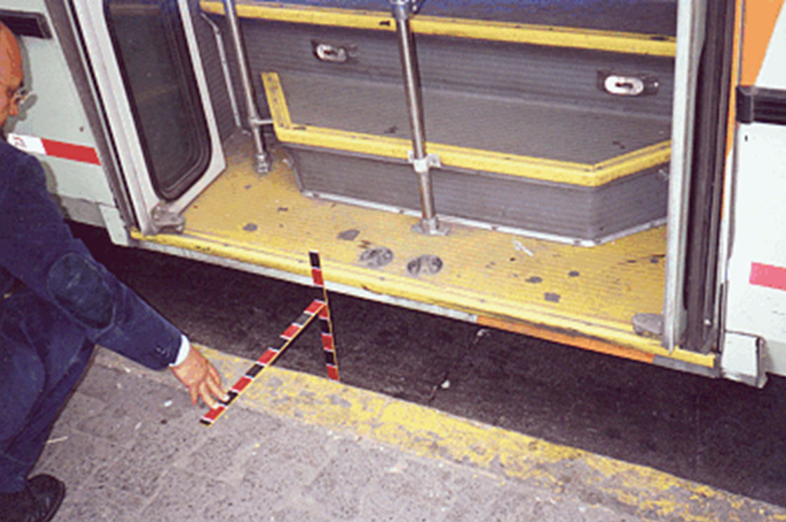
There is no combination of features that increases accessibility more than:
- Reducing both the vertical and horizontal distance between the station and the first step on the vehicle;
- Providing handrails parallel to the steps on both sides of the entrance and exit doors.
Research suggests that the combined horizontal and vertical distance to the first step of a vehicle should preferably not exceed 200 millimeters and definitely not exceed 300 millimeters (Department for Transport 2004). Handrails mitigate the problem of a high first step, even on older vehicles, by enabling frail or semi-ambulatory customers to better use their upper body strength.
30.6.4.2Kneeler and Flip-Out Step
Techniques to decrease the distance of the first step include “kneelers” and flip-out steps. A kneeler feature lowers the vehicle height of the vehicle by approximately 10 centimeters. A flip-out step effectively adds another step to the vehicle stairwell. Both facilitate more rapid boarding by all customers by lessening the height of the first step. They are especially useful when the vehicle cannot pull all the way to the curb, and customers must board from the street. They do not make the vehicle accessible to people in wheelchairs.
30.6.4.3On-board Ramps and Lifts
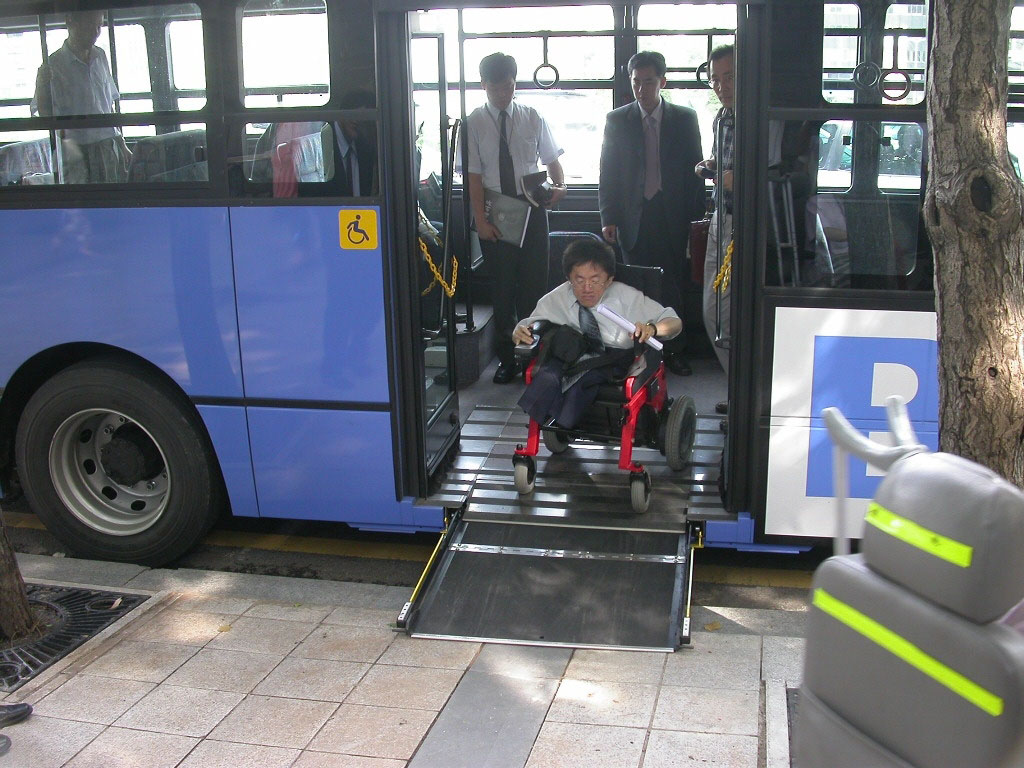
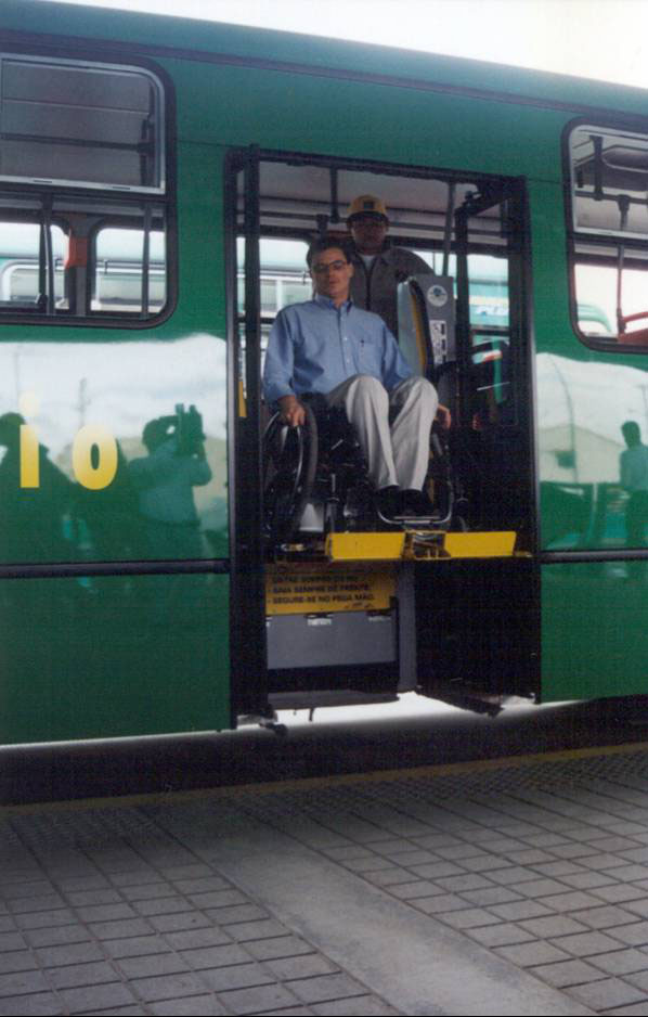
Ramps and lifts make a vehicle fully accessible to wheelchair users and others who require a level-change device. There are two typical types: flip-out and telescoping. Both require fairly consistent distances between the vehicle and stop or station. While they may have a reputation of slowing boarding and alighting, adhering to the following mitigates this.
- Locate at or under the front entrance of the vehicle, under direct supervision of the vehicle driver, without requiring the driver to leave his/her seat;
- Locate near the securement area;
- Designate boarding locations at the station or stop;
- Utilize safety features, such as hand grasps and edges or railings, to prevent wheelchairs from sliding off ramps or to keep them safely positioned on lifts while being raised to the vehicle floor, or lowered to the station. Such features should meet or exceed local requirements.
Table 30.5Various Ramp Dimensions (MacDonald 2006, p. 14)
| Element | Minimum | Preferred | Maximum |
|---|---|---|---|
| Ramp width | 750 mm | 800 mm | – |
| Typical horizontal extension | – | – | 1200 mm |
| Vertical rise | – | – | 300 mm |
| Vertical rise between telescoping sections | – | 0 mm | 6 mm |
| Lip at bottom of ramp | – | 0 mm | 15 mm |
Table 30.6Various combinations of ramp slopes and vehicle floor heights. Table modified from ADAAG.
| Slope | Maximum Height to Vehicle Floor above 150 millimeter Curb |
|---|---|
| 1:4 | 75 mm |
| 1:6 | 150 mm |
| 1:8 | 225 mm |
30.6.4.4Stations
Access by most seniors and customers with disabilities to complementary and feeder buses (even when inclusive design features are not yet phased in) can be greatly enhanced by systematically upgrading stations, beginning with those stations that are most used by all customers. Good station design can enable customers to more easily board vehicles, even when entrances are poorly designed. Good station design also enables the stations to become accessible to wheelchair users when lift- or ramp-equipped vehicles begin service.
Shelters and waiting areas benefit all customers, and especially assist seniors and those with disabilities. They provide protection from sun, rain, wind, and windblown particles. Illuminated shelters provide additional security at night, especially for women.
Stations can extend across a parking lane to the edge of the traffic lane. These “bus bulbs” or “boarders” can extend across a parking lane to the edge of the 2-meter curb extension, for example, allows the vehicle driver to get the vehicle close to and parallel to the curb so that the vehicle does not need to overhang the sidewalk. This in turn permits the station to be raised still further (e.g., 200 to 250 millimeters) to give better access to the first step of the vehicle.
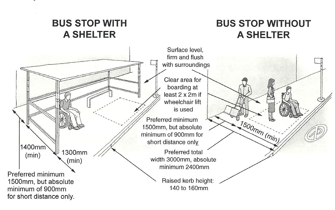
Box 30.1 Key Features
Figure 30.63 below illustrates key features, including a flat hard surface, minimum dimensions, a clear area for boarding, and a curb height, which reduce the distance to the first step of a vehicle if bus drivers are trained and monitored to properly station the bus adjacent to the stop and steps are taken to ensure that other vehicles do not park in the stop. An ischiatic support is shown, which substitutes for seats in low-cost installations. If adequate space for a shelter is lacking, the shelter can be placed at the rear of the sidewalk, for example, against the side of a building. The use of a beveled curb at bus stops may enable drivers to position their vehicles closer to the curb, as discussed in Section 30.5.
30.6.5Deployment
BRT systems are often faced with the questions of how to prioritize accessibility—that is, where to use accessible vehicles first.
Option 1: Deploy a few lift- or ramp-equipped vehicles on many or all lines.
In theory, a well-managed and reliable vehicle service with strict schedule adherence could serve a significant portion of travel demand by wheelchair users. It may also be more equitable, as opposed to initially concentrating accessible vehicles on one or two lines. The reality, however, is often less than ideal. Because this type of system must maintain a certain operational rigor, there are many opportunities for it to be unreliable. At best, this system should be reserved for temporary use.
Option 2: Phase in lift- or ramp-equipped vehicles on one line at a time, with all equipment accessible.
Focus on one line at a time during a transition to a fully accessible fleet. This increases the confidence of wheelchair users that they will not be subject to long delays, thus helping to market accessibility features. Public transport agencies may then focus on the line’s stops, stations, and surrounding infrastructure as well. Ideally, the most heavily travelled lines, or lines serving major trip generators such as universities, shopping, and residential centers, would be converted first.