22Roadway and Station Configurations
We will either find a way, or make one.Hannibal, military commander and politician, 247 BC–183 BC
Overview
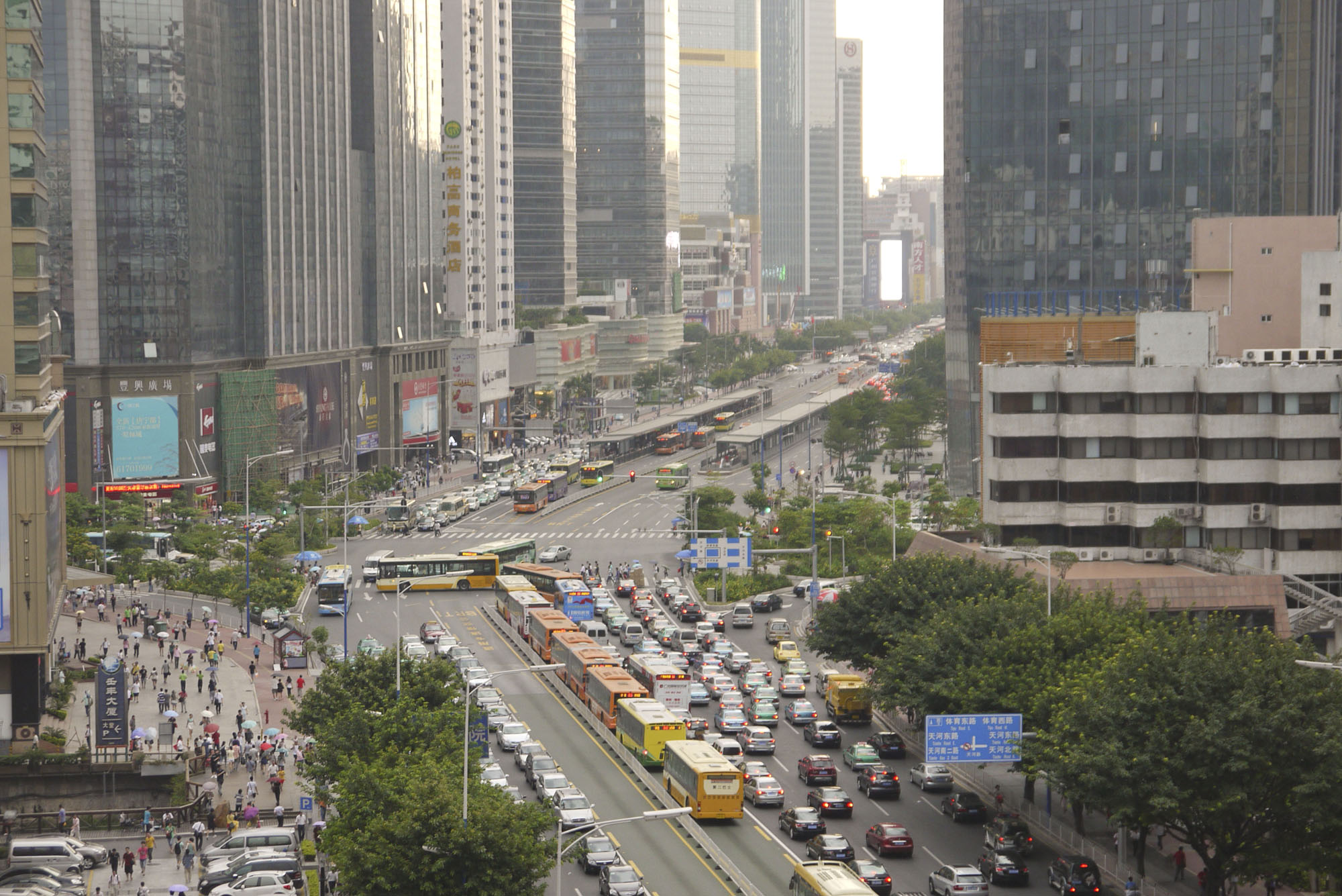
Creating optimal use of the available road reserve, or right-of-way, within a defined BRT corridor is the chief purpose of the design engineer (Figure 22.1). The first step to doing that is to create a conceptual design that is based on the sustainable transport hierarchy. First allocate space for walking trips, then cycling trips, then public transport trips, next service and freight trips, then taxi, then HOV, and finally the private car/motorcycle. While the rest of the chapter is about possible busway configurations, it is grounded upon the idea that pedestrian and cyclist access is paramount to a successful system. For more information about pedestrian and cyclist infrastructure design and integration, see Chapter 29: Pedestrian Integration and Chapter 31: Bicycle and Pedicab Integration.
To create the conceptual design, three frameworks need to be decided on:
- Cross-section design and integration: Will there be parallel bike lanes along the corridor? What is the minimum walkway width that is to be used in the design? Here you may decide upon typologies based on existing right-of-way;
- Busway configurations: Will the corridor be median aligned or run in one-way pairs? Different sections of the corridor may require different configurations. What type of separation will be used to protect the busway?
- Station and terminal configurations: Will the stations in the corridor be center stations or split? This decision will affect or be a result of the decision about the bus. Center stations require doors on the opposite side from the curb. Will there be passing lanes at the stations? This is a function of availability of space on the road and the needs of the service plan.
Other things to consider include the placement and design of the depot(s) (see Chapter 26), intermediate parking terminals, where buses can park during the times when frequency is not as high, the control center (Chapter 27), and the intersection and signal control (Chapter 24).
This chapter begins with a discussion of cross-section components and the creation of conceptual design assumptions. It then discusses the roadway configurations that can be applied in various design environments. Thereafter, the station placement considerations and options are reviewed.
The objective of this chapter is to equip the design engineer with the tools required to optimally locate and lay out the BRT infrastructure for the proposed BRT system within a given road corridor.
Terminology
- Busway: also known as runway or running ways, this is the segregated lane in which the BRT vehicles operate.
- Sub-stop: also known as module, a sub-stop is the basic unit of the station where BRT vehicles dock and customers get on and off, consisting of one or more docking bays.
- Docking bay: also known as stopping bay, this is the area in a sub-stop where the BRT vehicles pull up to allow customers to board or alight.
- Transfer station: also can be known as an interchange station, this is a station where customers can transfer from one service or route to another within the BRT system.
- Platform: the raised area where customers board or alight the buses after they pull up to the docking bay at the sub-stop. It is also the place where customers wait for the next bus.