22.3Station Configurations
Design is directed toward human beings. To design is to solve human problems by identifying them and executing the best solution.Ivan Chermayeff, graphic designer, 1932–
Stations are the critical linchpin between the customer and the system. Some of the attributes of BRT systems that distinguish them from conventional bus systems include pre-boarding fare collection and rapid and at-level boarding and alighting via multiple station doors into multiple doorway vehicles. The station design makes that happen.
When a busway approaches a station area, more roadway space is required due to the need for a station platform in addition to the busway lanes. A standard BRT station should be at least three meters wide (The BRT Standard awards 3 out of 3 points for appropriately wide stations). There are many possible ways of fitting a station into limited right-of-way.
- Building stations within medians: Sometimes a median already exists in the corridor. A median that is of a similar width as a proposed station is ideal since it represents unused space in the roadway. Some new roads, as in Dar es Salaam, Tanzania, are being constructed with wide medians, serving as placeholders for potential future BRT lines;
- Removing on-street parking spaces: If on-street parking has been retained, even after the dedication of bus lanes, it may be possible to remove some spaces in order to accommodate a station. This has the benefit of allowing removal of exactly the number of spaces that are needed to accommodate the station and the only result is a direct loss of parking spaces. Removing additional space from mixed traffic, on the other hand, even if in a very specific location, means a reduction in mixed-traffic throughput, which extends beyond that location;
- Removing left turn bays: Often, roadways widen at intersections in order to make room for dedicated left turning bays. It is thus possible to remove the left turning bays and replace them with a station. Removing left turns has the added benefit of eliminating a mixed-traffic phase at intersections, with the result of increased bus throughput at the intersection (The BRT Standard rewards removal of left turns across the intersection with maximum points).
- Building stations where there is land readily available: While it is always recommended to build stations where the highest demand exists, within that framework it can be reasonable to select an exact location in which there is open land available. At that place, the road can be widened to make way for a station. Ideally, the land that is taken will have been of marginal use to the community. For example, it may be possible to acquire off-street surface parking lots and widen for stations there. This option is less desirable when it is viable businesses or residences that must be acquired. However, this is sometimes done as well, provided it is accompanied by careful and responsible outreach to the affected community (see Chapter 10: Participation and Outreach);
- Creatively configuring stations: There are a variety of station configurations that may fit better into particularly constrained roadways. These are described in the following section.
It is not recommended, however, to reduce the width of sidewalks in order to accommodate stations, since pedestrian volumes will only grow, not shrink, with the introduction of a BRT station.
If passing lanes are included in the design, there is an even greater need for additional roadway space. In some cases, such as on 80th Street (Calle 80) in Bogotá, passing lanes are provided throughout the entire corridor since the road was wide and space was not constrained. However, this is very rarely the case. Where constraints exist, most of the same principles bulleted above for accommodating stations may apply. However, because passing lanes are an additional draw on roadway space, a combination of these techniques may be needed.
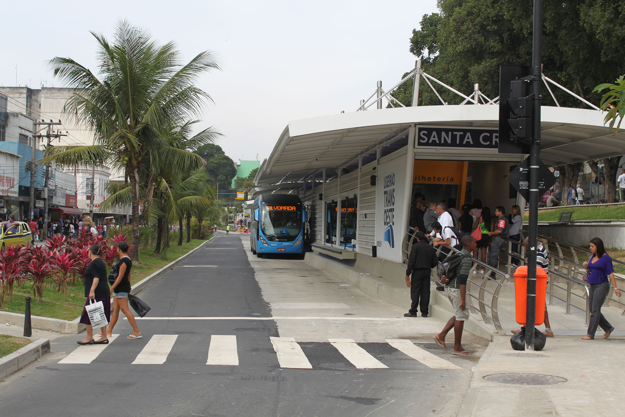
Additionally, it is possible to include passing lanes only at critical passing points rather than along the entire length of the corridor if right-of-way is constrained. The BRT Standard awards 4 out of 4 points for providing passing lanes at BRT stations, and does not further incentivize full-corridor passing lanes. On the TransOeste corridor in Rio de Janeiro (Figure 22.44) a passing lane is provided only at station areas. Outside the station areas, only a single lane of busway is provided for each direction of travel.
22.3.1Station Types
There are three main station types that are based on the function or role they play in the system:
- Standard: the configuration and structure of a standard station depends on the capacity needed for both customer and vehicle volumes expected at that station;
- Transfer: a structure that fulfills the role of a standard station and facilities transfers either within the system to another trunk route or a feeder route or to another system, like metro. Ideally this happens without leaving the structure—physical integration—but may not be possible due to space constraints;
- Terminal: a structure that represents the endpoint of a corridor. Usually space is available for a larger facility that can easily accommodate physical integration of feeder and trunk lines. With direct services becoming more popular, large terminal structures may not be as necessary.
Stops, which are usually defined as having a totem and/or a bus shelter, but no real infrastructure, can occur as well, but usually when the direct services buses are operating off the trunk corridor or when the stations on a trunk route need to integrate into dense downtowns, like on Line Four in Mexico City. It is important to ensure that these are branded as part of the system and can be distinguished from regular bus services. Stops are not usually recommended for BRT systems.
When designing the roadway, the design team should take into consideration the role a particular station will perform upon opening and potentially in the future as the system expands. Upon the opening of line 1, a station may function as a standard station but line 3 will intersect line 1 at that station. Having the space and flexibility to adjust the role of the stations as the system expands will be key. Planning for the infrastructure required for that standard station to become a transfer station can be incorporated into the design process for the roadway. Key aspects of service planning, such as the frequency of the services that coincide at the station and customer transfers, should lead the design of the facility. Ideally services are designed to minimize the number of transfers, which is beneficial to the customer, but can also help reduce the need for large transfer stations.
Standard Stations
The role of a standard station is to be the interface between the customer and the system, through fare collection and allowing access, providing at-level boarding, information about the services. A station should be safe and weather protected. A station can serve as a community focal point. In Ahmedabad, India, when Janmarg opened, its stations were called the city’s best public spaces.
A station typically has the following components:
- Transition areas: the areas that are not directly spaces for boarding and alighting but can include kiosks for buying tickets, seating areas, etc. These are areas where customers can find information about the system;
- Docking bays: this is where the bus pulls up in order to let customers on and off.
- Sub-stops: also known as modules, stations may contain multiple sub-stops that can connect to one another but should be separated by a walkway long enough to allow buses to pass one sub-stop to dock at another. A station may be composed of only one sub-stop.
- Platform: this is the main area where customers wait to board and where they alight. For conceptual design, an average width of five meters is used to estimate the cross section of a center-aligned station. If split, each station is about 3 meters. Platform height will depend on the type of bus being procured or used, which is usually a function of the financial model;
- Passing lanes.
As a baseline, every station has one sub-stop with two docking bays. Above that, sizing the station should be a function of the operational plan and projected peak customer volume. The peak number of boarding and alighting customers will determine how much station floor space will comfortably accommodate all customers. The operational plan for a particular BRT corridor will dictate whether a single sub-stop will be able to accommodate the planned number of vehicles using the station during a peak period, or whether multiple sub-stops will be required due to high vehicle frequencies or multiple vehicle routes (Figure 22.46).
In order for multiple stopping bays to function properly, and for services to be split between various local and limited-stop routes, vehicles must be able to pass one another at the stations. Passing lanes allow buses approaching the station to pull around docked buses to available docking bays and not sit in queue. Therefore, sub-stops need to be spaced at least 1.7 times the vehicle length from each other in order to allow for buses to bus in or out of the sub-stops. These details of station design are described in more detail in Chapter 25: Stations and Terminals.
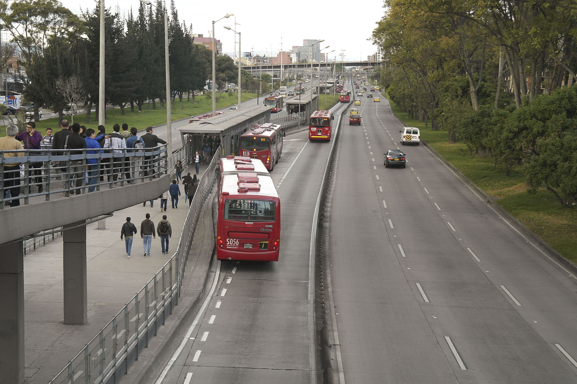
The passing lane may exist as just a second lane in the station area, or the additional lane may be extended all along the corridor (Figure 22.47). Whether the second lane is needed beyond the station area depends on the saturation levels along the corridor, and especially depends on the level of congestion at intersections.
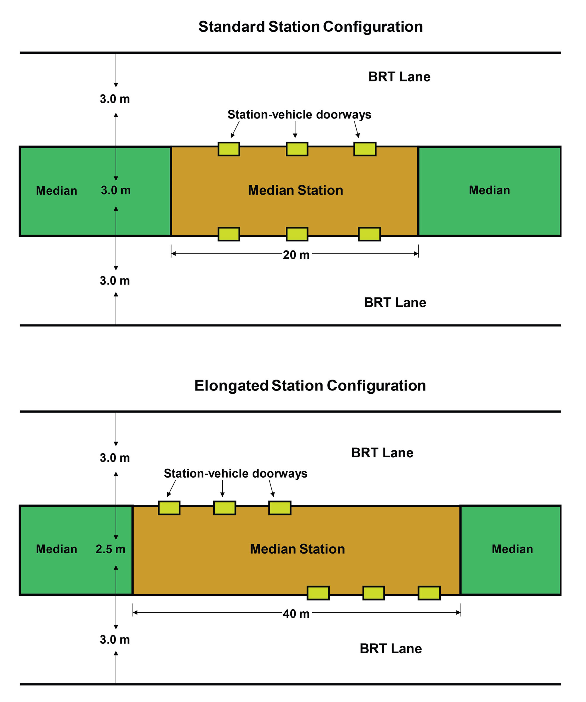
The principal difficulty in including a passing lane is the impact on road space. The additional lane in each direction would seem to require a road width few developing cities can reasonably provide. However, a staggered station design can help permit passing lanes, even in relatively tight corridors. In this case, the sub-stops for each direction of travel are offset. The preferred median station design is retained, but its shape is elongated to help accommodate the passing lane. Customers can still change directions within the closed station area by crossing a connecting platform. In this case, the higher customer flows within the stations are achieved by lengthening the stations instead of widening them.
Other options for accommodating passing lanes in relatively narrow roadways include reducing mixed-traffic lanes as well as making property purchases for widening. In some BRT cities, such as Barranquilla, Colombia, plans call for the purchase of properties near station areas. The road infrastructure is widened in these areas in order to accommodate the passing lane. This same strategy is being proposed for some stations in the Dar es Salaam, Tanzania, system. The viability of property purchases for this purpose depends on local property costs as well as the existence of a well-designed compensation program for property owners.
Transfer Stations
These stations have to meet the needs of a standard station, but also address transfers, whether between feeder and trunk routes, between other trunk routes, or between other modes. The space requirements may be greater, or the connecting infrastructure may be additional and more costly.
Feeder connections to the trunk lines do not necessarily occur only at major terminal facilities. When feeders intersect the trunk corridors outside of terminals, due to space constraints, it may be difficult to have a seamless integration where the customer remains in a paid-fare area and does not have to re-enter the system between feeder and trunk due to space constraints. Thus, a bit of creativity is required to design and control the transfer process.
In addition to feeder connections, transfer stations can also link two different trunk lines. As a system expands across a wider network, more opportunities to link different corridors of the BRT system will occur. There are several options for facilitating transfers between corridors. These options include:
- Platform transfers;
- Underground tunnels/overhead pedestrian bridges;
- Interchange facility (multi-bay or multi-story facility).
A system may use a combination of these interchange options, depending on the local circumstances at the interchange point.
U-turn facilities may be needed as these stations are often the termination points of either trunk or feeder routes. The U-turn movement of vehicles requires additional road reserve width, a consideration when locating these facilities. In addition, an area is required in close proximity to these stations for the holding of off-duty buses, or buses waiting for their departure time on their schedule. Staff facilities may also be required for drivers changing shift, ablution facilities, and accommodation for a localized dispatch.
22.3.2Station Configurations
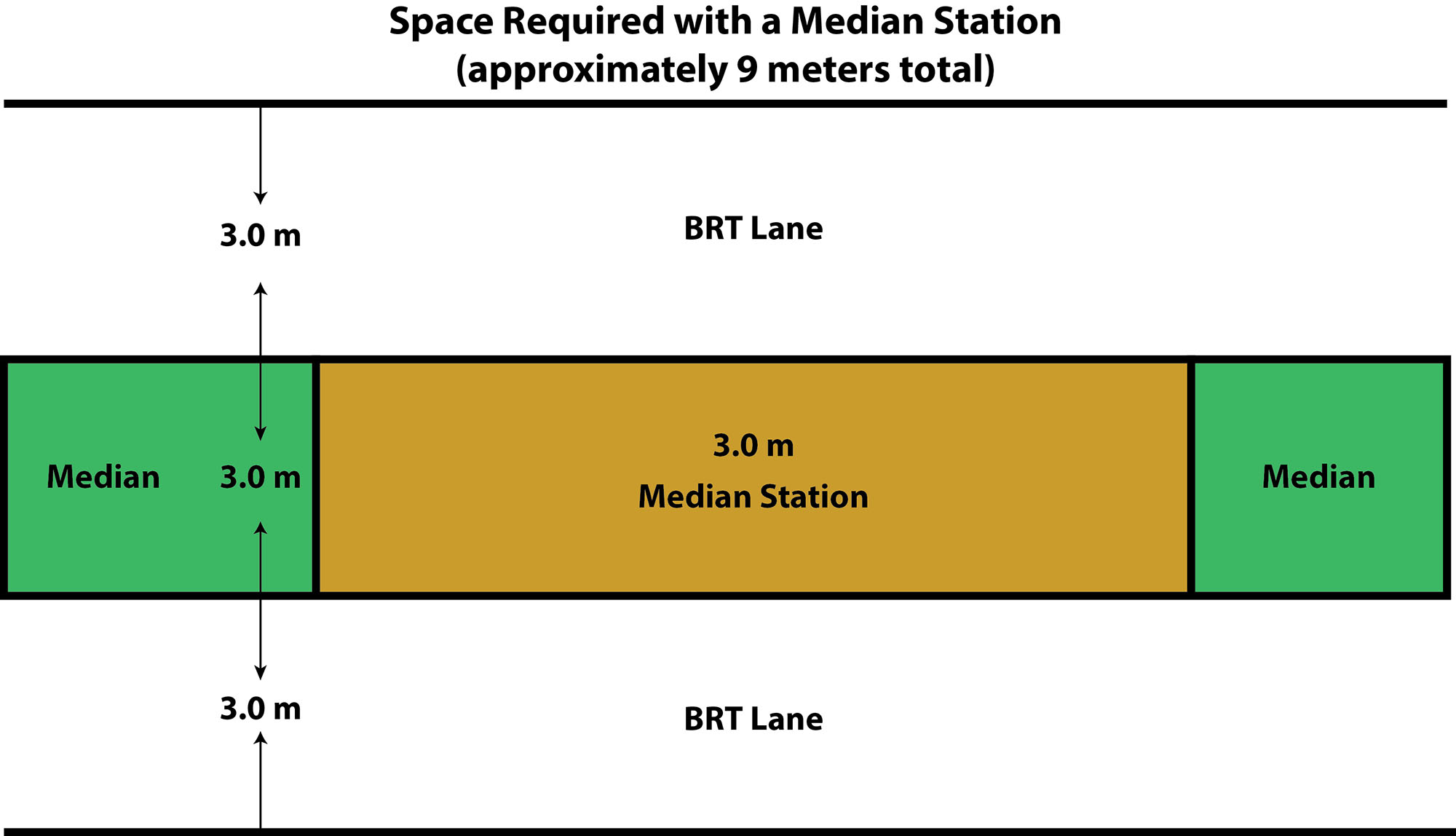
There are two main ways of configuring BRT stations: either as center or as split, side-aligned stations. Within those, there are options to address roadway availability and/or constraints.
Center
Center stations are located in the middle of the busway and typically require buses with doors on the opposite side from conventional buses that normally have doors on the curbside. While requiring a somewhat wider floor area and buses with doors on the opposite side, the single station in the median is by far the most useful in terms of customer convenience and system design. With a single station serving both directions, customers are able to change directions by simply crossing the station platform.
Where road width is a constraint, there are two main options with center configurations: elongated and offset. Width is harder to add, while length is easier.
Elongated
One way to address the need for width, which is based on the peak customer demand, is to elongate the station so that the docking bays for the buses from each direction are not directly across from each other. If the station doors for each direction are situated directly opposite one another, then when two buses dock at the same time, the competition for that space increases and it may become too congested, in which case, the station size must be increased to meet the capacity demand.
Alternatively, the station itself can be elongated to offset the placement of the station doors for each service direction. Thus, instead of the station doorways being directly opposite one another for each corridor direction, the doorways are staggered somewhat (Figure 22.49). In order to accommodate this doorway configuration, the stations must be somewhat longer than a station with doorways directly opposite one another (Figure 22.49). However, the advantage is a reduction in the required station width. Quito’s Ecovía corridor makes use of this technique in order to fit the system into a relatively narrow roadway (Figure 22.50). Thus, an elongated station configuration allows a fairly narrow station with the favored median station location. On the other hand, it is generally agreed that a narrower station is less comfortable for customers.
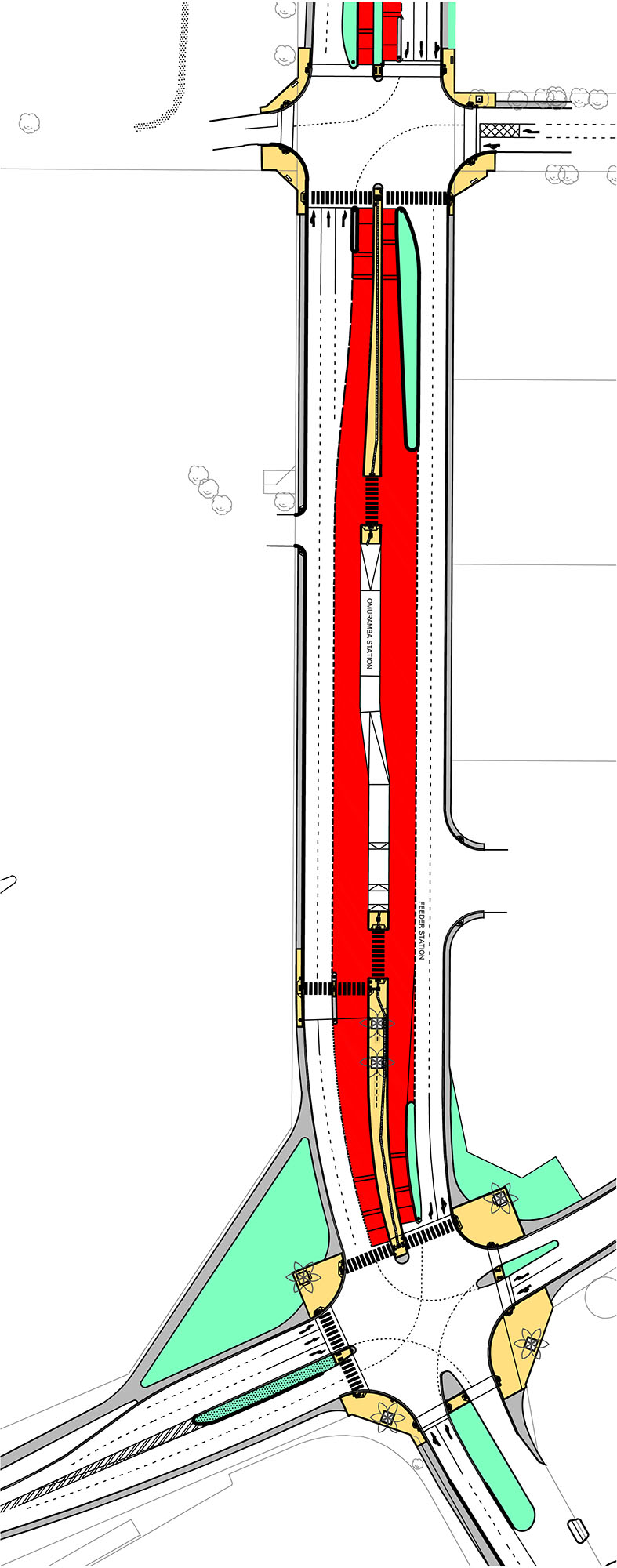
Off-Set Stations
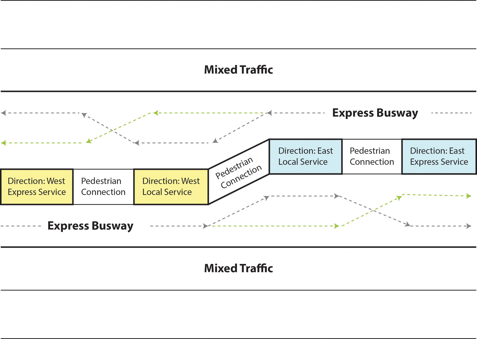
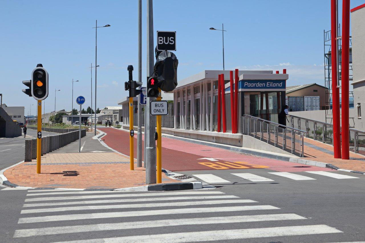
Another way to address constraints in road width with a center-aligned configuration is to off-set the directions of travel into two separate sub-stops, so that each sub-stop only allows for docking in one direction of travel. This still allows buses to dock and transfer customers in both directions of travel, including passing lanes. However, each sub-stop only allows for docking in one direction of travel. This configuration reduces the required road width by one lane and still delivers full passing capabilities at the station. Of course, this configuration does elongate the station footprint and also introduces a slight turn at the station area. Nevertheless, in cities with restricted road widths, this design can be effective in allowing passing lanes at stations. Cape Town, South Africa, has applied this concept on its Atlantis corridor (Figure 22.53).
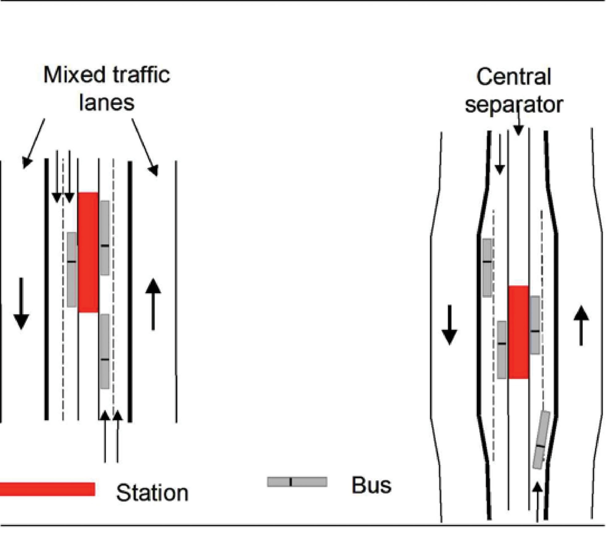
Split, Side-Aligned Station Configuration
Split stations are located adjacent to the busway along the side, with each station serving just one direction. This type of configuration allows the use of existing bus fleets with doors on the curb-side boarding, and a new fleet with left-side doors may not be required. The benefit is then that all existing bus services already on or near the corridor may continue to use the corridor since existing bus fleets can be used for each service. In the United States, this is often the selected course since most cities already own large bus fleets with right-side doors. However, some cities are beginning to consider procuring left-side or dual-side boarding buses as a standard practice whenever new buses are required anywhere in their systems.
Split stations will require either complicated connecting infrastructure (underground pedestrian tunnels or overhead pedestrian bridges) or a more costly fare system to recognize customers leaving and reentering the system from nearby stations. It may also cause confusion to users new to the system (they may get lost or lose their paid fare). Additionally, building two stations instead of a single median station will tend to increase overall construction costs and may require more road space. To address space constraints, split stations can be staggered.
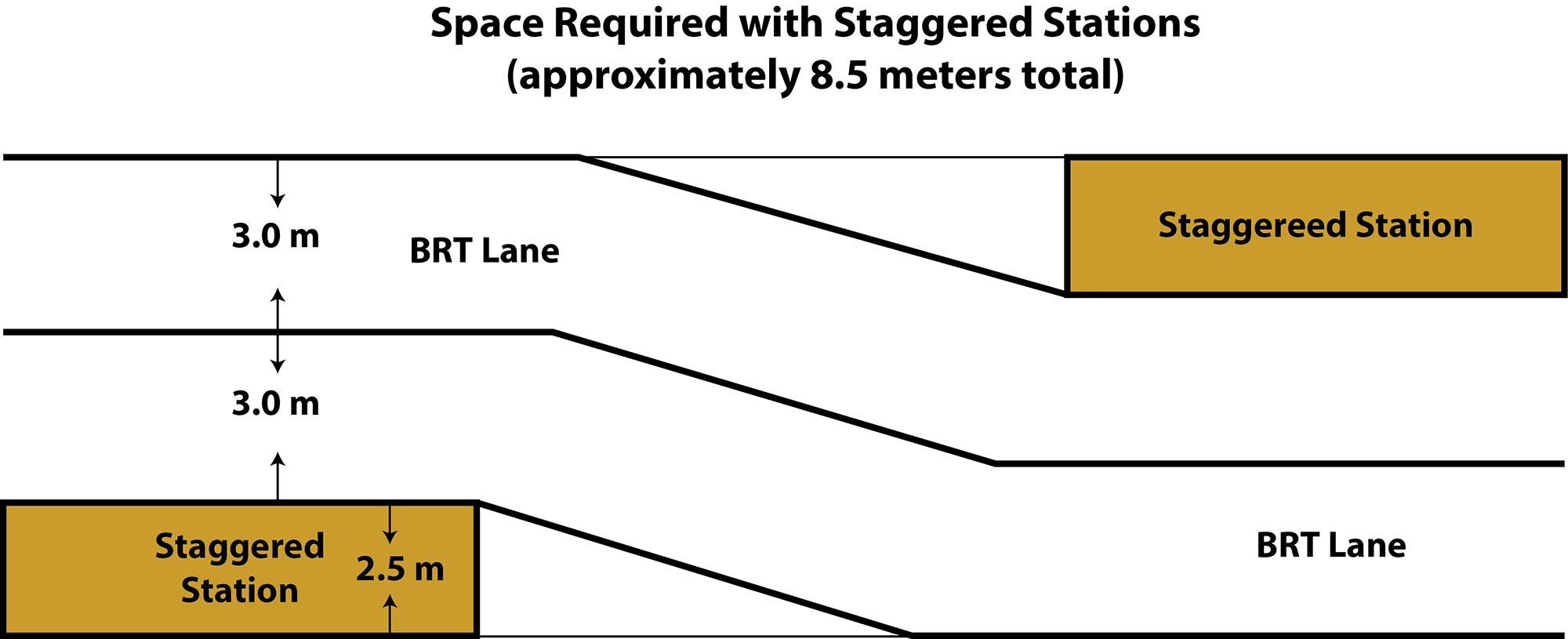
Staggered
The staggering of split stations for each direction may provide marginal space savings in terms of road width. The station will have to accommodate approximately half as many customers for a single direction, and thus a reduction in width is possible (though a reduced width can feel uncomfortable for customers). The marginal width gained from a staggered configuration, estimated at 0.5 meters, is not significant, and given the operational advantages of center-aligned stations, they are recommended over split stations. For those reasons, split stations receive no points in The BRT Standard.